System and method for bracketing and removing tissue

a tissue bracketing and tissue technology, applied in the field of tissue bracketing and tissue removal, can solve the problems of difficult for surgeons to detect the exact depth of the lesion, the technique is not optimal, and the margins of tissue to be removed are difficult to properly define, so as to reduce the mobility of tissu

Inactive Publication Date: 2005-03-17
VARIAN MEDICAL SYSTEMS
View PDF99 Cites 95 Cited by
  • Summary
  • Abstract
  • Description
  • Claims
  • Application Information

AI Technical Summary

Benefits of technology

[0013] Still another aspect of the present invention is a tissue anchor for reducing mobility of tissue during surgical or other procedures. The tissue anchor includes an elongate tube having a central bore, a distal end and a proximal end. The tube comprises at least one aperture adjacent the distal end. The tissue anchor also has an elongate member with a portion sized for receipt and axial movement in the central bore between a first position and a second position. The portion has a distal end and the elongate member includes at least one anchor member attached to the portion adjacent the distal end. In addition, the at least one anchor member is sized and positioned so that when the portion is in the first position the at least one anchor member is at least partially received in the elongate tube and when the portion is in the second position the at least one anchor member projects through the at least one aperture.

Problems solved by technology

The surgeon does not cut along the shaft of the needle from the skin because the distance is too great.
This technique is not optimal.
Due to the amorphous and highly pliable nature of certain tissue, e.g., breast tissue, it can be difficult to properly define the margins of tissue to be removed, both during and after insertion of the needle(s).
Also, it is often difficult for the surgeon to detect the exact depth of the lesion based on the placement of the needles.
In other cases, as a result of the difficulty of estimating the proper location of the boundaries of the volume of tissue to be removed, the lesion ends up being eccentrically positioned within the volume of tissue excised.
In still other cases, more normal tissue is removed than is required, which is disadvantageous in this era of tissue-conserving therapies.
Unfortunately, the devices described in the '431 and '329 patents are vastly more complex, and hence expensive, than is appropriate for many surgical procedures, particularly with the emphasis on cost containment in managed health care.
Furthermore, due to the amorphous, pliable nature of certain tissue, the systems of the '431 and '329 patents cannot be used effectively.
These systems generally function effectively when the devices defining the body portion of interest are inserted in bone, e.g., in a skull in connection with brain surgery or treatment, but are not believed to operate as intended when the devices are inserted in amorphous, pliable tissue.
It tends to be difficult to manipulate the scalpel within this opening so as to remove the desired volume of tissue.
Circular cutting tools are not widely used in surgery.
While use of the ABBI tool is believed to be a relatively effective way to perform a core biopsys of breast tissue, it is not apparently designed to remove cylinders of tissue having a diameter much in excess of about 20 mm.
As such, it is not adapted for use in surgeries involving the removal of relatively large tissue portions in a single cutting sequence.
In addition, the ABBI tool's effectiveness in therapeutic, rather than diagnostic, surgeries has not been confirmed.
Even with the systems and techniques described above, it remains difficult for a surgeon to remove a tissue mass in amorphous, pliable tissue, such as breast tissue, so as to ensure the entire tissue mass is removed while at the same time removing only minimal portions of adjacent tissue.

Method used


Image

  • System and method for bracketing and removing tissue
  • System and method for bracketing and removing tissue
  • System and method for bracketing and removing tissue

Examples


first embodiment

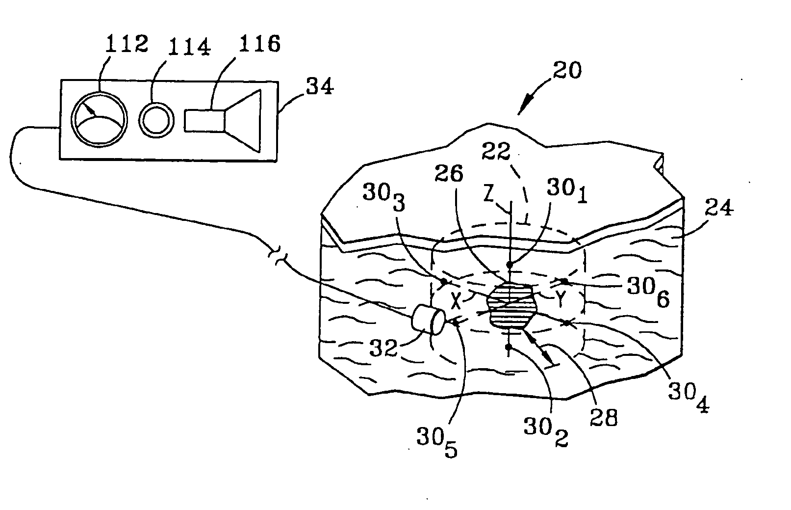
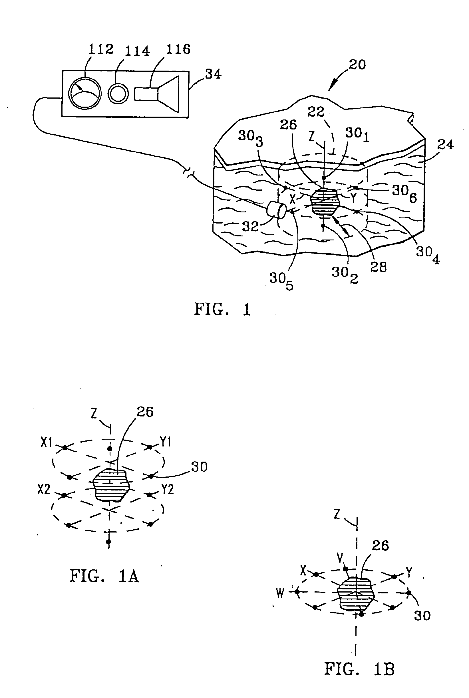
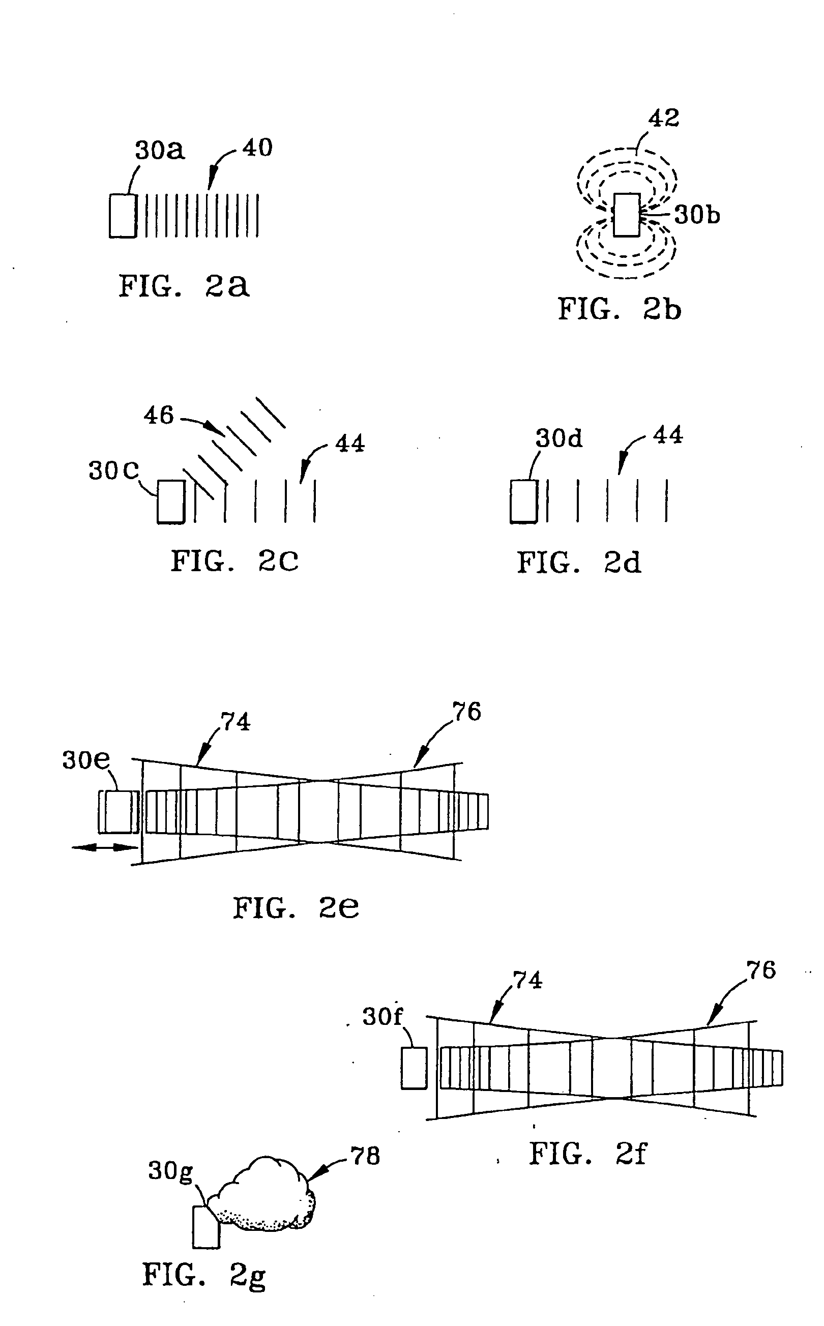
[0048] In addition, markers 30 each have a detection characteristic to enable detection by probe 32 and detector 34. The detection characteristics of the various embodiments of markers 30 can be characterized as active or passive. In the active category, the detection characteristic of marker 30, illustrated in FIG. 2a as marker 30a, is gamma rays 40. In this regard, marker 30a may include materials such as technetium 99, cobalt isotopes or iodine isotopes. Such materials may be obtained from DuPont of Billerica, Mass. Preferably, each marker 30a generates gamma rays 40 having a field strength in the range of 1-100 microCurries.

[0049] Also in the active category, in a second embodiment of marker 30, illustrated in FIG. 2b as marker 30b, the detection characteristic is magnetic field 42. Markers 30b of the second embodiment thus contain ferromagnetic materials in which a magnetic field can be induced, or alternatively are permanently magnetized and so have an associated permanent mag...

third embodiment

[0050] Referring to FIG. 2c, in a third embodiment, again in the active category, marker 30c emits radio frequency (“RF”) signal 44 in response to a triggering signal 46. Various energy sources may be used for triggering signal 46, including a magnetic field, ultrasound or radio frequency energy. In this latter case, marker 30c is preferably designed to receive triggering signal 46 which has a first RF wavelength, and in response thereto, emit signal 44 of a second RF wavelength. In the simplest case, no data, other than the specific radio frequency itself, is carried in signal 44. Alternatively, markers 30c may all transmit signal 44 at a single frequency, with data uniquely identifying each marker being carried in signal 44 emitted by each marker.

[0051] A suitable marker 30c is illustrated in FIG. 3a. This marker 30c includes a transmit / receive antenna 52 for receiving an RF signal at a first frequency and transmitting an RF signal at a second frequency. Also included is a power d...

fourth embodiment

[0053] In a fourth embodiment, again in the active category, marker 30d, illustrated in FIG. 2d, continuously emits signal 44 at specific frequencies in the radio frequency spectrum. The marker 30c illustrated in FIG. 3a and described above can be satisfactorily employed as marker 30d by adding a battery (not shown) in place of power detector portion of circuit 54 of marker 30c. RF exciter 60 is not required in connection with marker 30d, insofar as the battery generates the energy used by the marker in producing RF signal 44.


PUM


Abstract

A system and method for bracketing a tissue volume (22) and later locating the bracketed tissue volume. The system includes a plurality of markers (30) and a probe (32) and detector (34) for use in locating the markers by providing information usable by a surgeon that is representative of changes in proximity between the probe and the plurality of markers. The markers have various detection characteristics, e.g., they transmit gamma rays, that are detectable by an associated probe and detector. The tissue volume is removed by manipulating a cutting tool based on the proximity information provided by the detector which can be used by the surgeon to define the boundary of the tissue volume. A two-part cutting tool (200) is provided for removing the tissue volume, and a tissue anchor (300) is provided for stabilizing the tissue during removal. The system and method of the invention are particularly useful in bracketing and then removing a tissue volume from amorphous, pliable tissue such as breast tissue.

Description

FIELD OF THE INVENTION [0001] The present invention relates to a system for and method of bracketing a tissue volume containing a tissue mass, e.g., a non-palpable breast tumor, using markers to define the boundary of the tissue volume and a probe and detector to locate the markers. The present invention also pertains to a method of removing the bracketed tissue, a circular cutting tool for removing tissue in connection with this and other methods, and a tissue anchor for reducing mobility of tissue during tissue removal procedures. BACKGROUND OF THE INVENTION [0002] A current technique for performing an excisional biopsy of a non-palpable breast lesion that has been identified by mammogram or other method involves placement of a needle or guide wire (e.g., a “Kopanz wire”), with or without blue dye, to guide the surgeon to the lesion. The tip of the needle is generally placed directly in or as close as possible to the lesion. When larger or more complex lesions are encountered, two...

Claims


Application Information

Patent Timeline
Patent Type & Authority Applications(United States)
IPC IPC(8): A61B8/08A61B17/00A61B10/02A61B17/32A61B17/34A61B19/00
CPCA61B17/3201A61B2019/5495A61B17/3211A61B17/3403A61B19/5244A61B19/54A61B2017/00349A61B2017/320064A61B2017/3413A61B2019/5263A61B2019/5408A61B2019/542A61B2019/5429A61B2019/5437A61B2019/545A61B2019/5454A61B2019/5458A61B17/32053A61B2034/2063A61B2090/392A61B2090/3995A61B34/20A61B90/39A61B2090/3908A61B2090/3929A61B2090/3937A61B2090/395A61B2090/3954A61B2090/3958
Inventor KRAG, DAVID N.
Owner VARIAN MEDICAL SYSTEMS
Why Eureka
Try Eureka