This helps you quickly interpret patents by identifying the three key elements:
Problems solved by technology
Method used
Benefits of technology
[0026] In contrast to the marker clips as described above, the cavity marking device has the obvious advantage of marking the geometric center of a biopsy cavity. Also, unlike the marking clip which has the potential of attaching to loose tissue and moving after initial placement, the marking device self-expands upon insertion into the cavity, thus providing resistance against the walls of the cavity thereby anchoring itself within the cavity. The marking device may be configured to be substantially smal
Problems solved by technology
In some cases, however, the physician may be concerned that the initial biopsy failed to remove a sufficient amount of the lesion.
This device has significant drawbacks.
If the limbs have been prematurely bent together, the clip will be discarded since it will most likely not attach properly to the cavity wall.
Additionally, there is always the possibility that the clip may detach from the cavity wall during or after withdrawal of the tools used to place the clip into the cavity.
Aside from the problems inherent in the placement of the marking clip, there are also limitations associated with how well the marking clip can identify a biopsy cavity.
Moreover, patient concern limits the number of clips that may be placed in a cavity.
Obviously, determination of the periphery of a biopsy cavity from one point of the periphery is not possible.
These limitations are compounded as the biopsy cavity fills within a few hours with bodily fluids, which eventually renders the cavity invisible to non-invasive techniques.
Another difficulty in viewing the clip ste
Method used
Image
Click on the blue label to locate the original text in one second.
Reading with bidirectional positioning of images and text.
Examples
Embodiment Construction
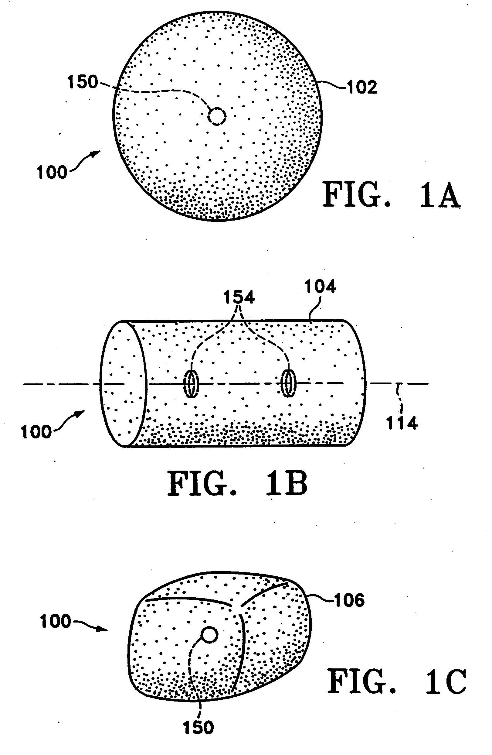
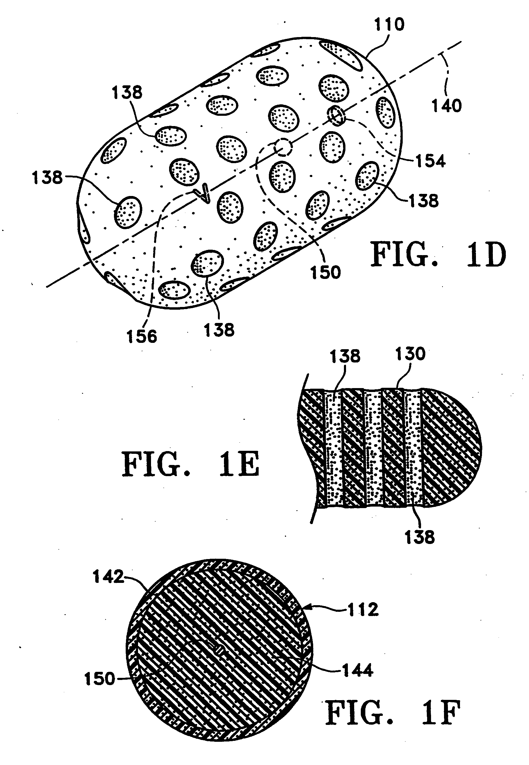
[0046]FIGS. 1A-1C show various configurations of a preferred subcutaneous cavity marking device of the present invention. Here the marking device (100) is displayed as having either a generally spherical body (102) (FIG. 1A), a generally cylindrical body (104) (FIG. 1B), or a multi-faced or irregular body (106) (FIG. 1C). In general, it is within the scope of this invention for the body to assume a variety of shapes. For example, the body may be constructed to have substantially curved surfaces, such as the preferred spherical (102) and cylindrical (104) bodies of FIGS. 1A and 1B, respectively. The body may have conical or ellipsoidal, etc., shapes as well. It is further within the scope of this invention for the body to have substantially planar surfaces, such as polyhedric (i.e., cubic, tetrahedral, etc.) or prismatic, etc., forms. Finally, the body may also have an irregular or random shape, in the case of a gel, combining features of various curved and planar surfaces. Body (106...
PUM
Abstract
These are biopsy cavity marking devices and methods. The devices and methods include a bioabsorbable filler body and a detectable marker attached to the filler body, where the detectable marker has a predetermined shape. The detectable marker may be mammographic, radiopaque, echogenic, or palpable. The predetermined shape may be non-spherical, a barb, a sphere, a ring, a wire, or a band. It may also be affixed to the interior of the body or to the surface of the body. In another embodiment, the device may include a bioabsorbable filler body and a detectable marker attached to the filler body, where the detectable marker is a wire. Methods of using these devices to mark a biopsy cavity are also included.
Description
[0001] This is a continuation of U.S. application Ser. No. 10 / 114,712, filed Apr. 1, 2002, which is a continuation of U.S. application Ser. No. 09 / 805,652, filed March 13, 2001, which is a continuation of U.S. application Ser. No. 09 / 285,329, filed Apr. 2, 1999, now U.S. Pat. No. 6,356,782, which is a continuation-in-part of U.S. application Ser. No. 09 / 220,618, filed Dec. 24, 1998, now abandoned. All of the above patents and applications are incorporated herein by reference in their entirety.FIELD OF THE INVENTION [0002] This invention is directed to subcutaneous cavity marking devices and methods. More particularly, a cavity marking device and method is disclosed that enable one to determine the location, orientation, and periphery of the cavity by radiographic, mammographic, echographic, or other non-invasive techniques. The invention typically is made up of one or more resilient bodies and a radiopaque or echogenic marker. BACKGROUND OF THE INVENTION [0003] Over 1.1 million brea...
Claims
Application Information
Patent Timeline
Application Date:The date an application was filed.
Publication Date:The date a patent or application was officially published.
First Publication Date:The earliest publication date of a patent with the same application number.
Issue Date:Publication date of the patent grant document.
PCT Entry Date:The Entry date of PCT National Phase.
Estimated Expiry Date:The statutory expiry date of a patent right according to the Patent Law, and it is the longest term of protection that the patent right can achieve without the termination of the patent right due to other reasons(Term extension factor has been taken into account ).
Invalid Date:Actual expiry date is based on effective date or publication date of legal transaction data of invalid patent.