
Congestion management in telecommunications networks

Inactive Publication Date: 2005-03-17
AVAYA INC
View PDF35 Cites 1 Cited by
  • Summary
  • Abstract
  • Description
  • Claims
  • Application Information

AI Technical Summary

Benefits of technology

The present invention is a technique for lessening the likelihood of congestion in a congestible node without some of the costs and disadvantages for doing so in the prior art. In accordance with the illustrative embodiments of the present invention, one node—a proxy node—drops protocol data units to lessen the likelihood of congestion in the congestible node.
The illustrative embodiment of the present invention is useful because it enables the manufacture of “lightweight” nodes without large queues and without the horsepower needed to run an algorithm, such as Random Early Discard or Random Early Detection, for deciding which protocol data units to drop. Furthermore, the illustrative embodiment is useful because it can lessen the likelihood of congestion in legacy nodes.

Problems solved by technology

In other cases, a protocol data unit might spend a long time.
When a queue is filled, the attempted addition of protocol data units to the queue causes the queue to “overflow” with the result that the newly arrived protocol data units are discarded or “dropped.” Dropped protocol units are forever lost and do not leave the network node.
The loss of a protocol data unit has a negative impact on the intended end user of the protocol data unit, but the loss of any one protocol data unit does not have the same degree of impact as every other protocol data unit.
In other words, the loss of some protocol data units is more injurious than the loss of some other protocol data units.
Some legacy nodes, however, were not designed to intentionally drop a protocol data unit and it is often technically or economically difficult to retrofit them to add that functionality.
Furthermore, it can be prohibitively expensive to build nodes that have the computing horsepower needed to run an algorithm such as Random Early Discard or Random Early Detection.

Method used

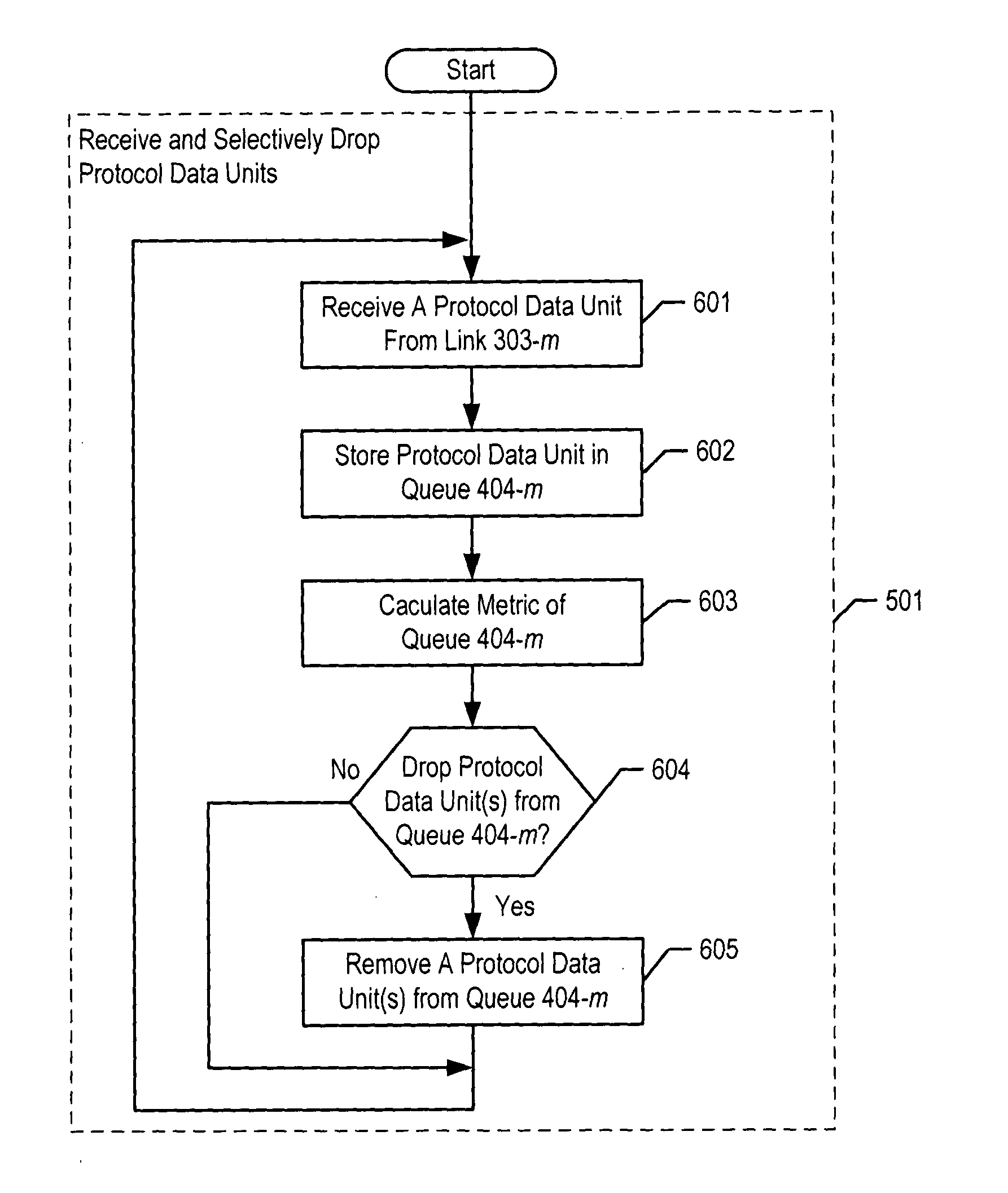

Image

  • Congestion management in telecommunications networks
  • Congestion management in telecommunications networks
  • Congestion management in telecommunications networks

Examples


Embodiment Construction

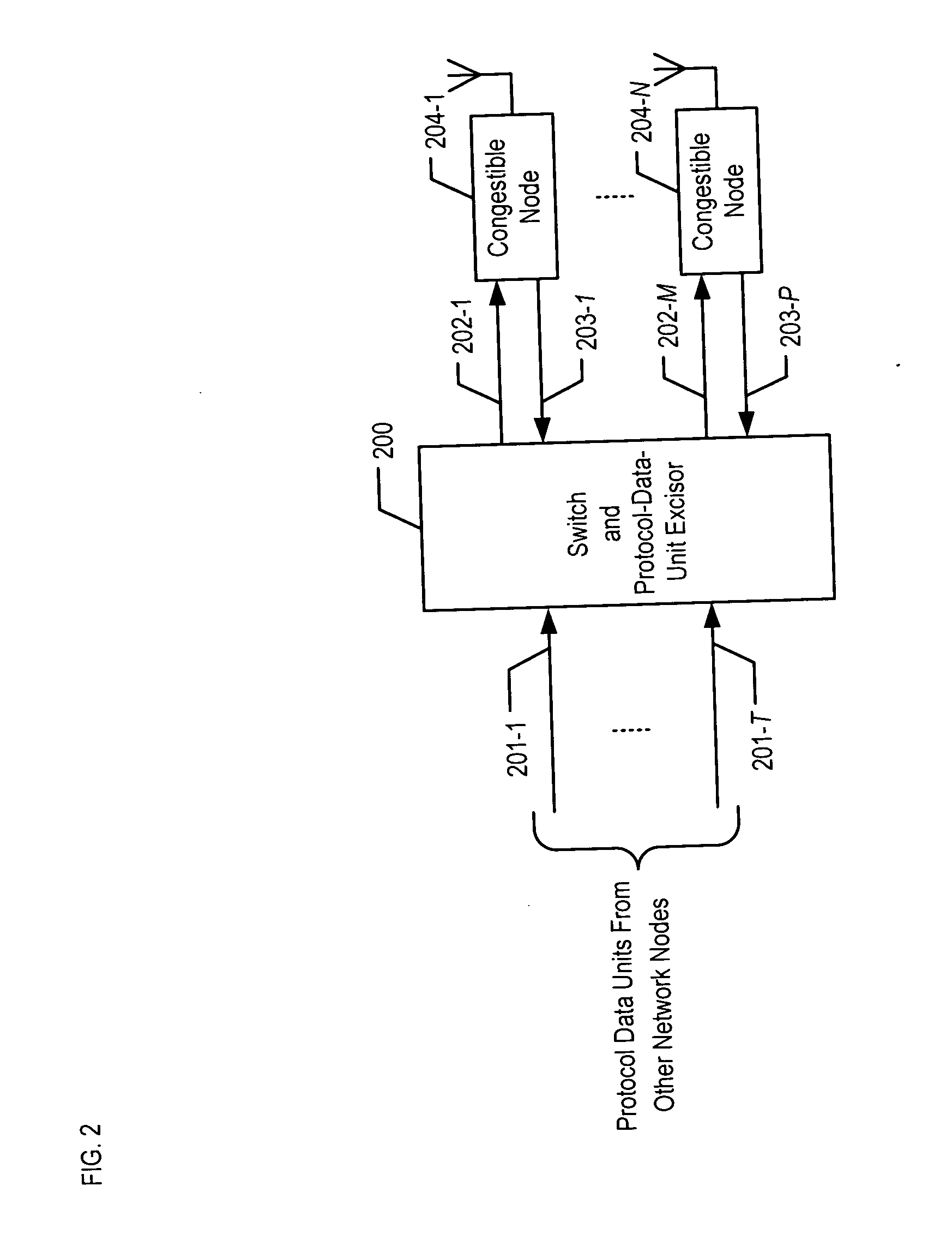
FIG. 2 depicts a block diagram of the illustrative embodiment of the present invention, which is switch and protocol-data-unit excisor 200. Switch and protocol-data-unit excisor 200 comprises inputs 201-1 through 201-T, outputs 202-1 through 202-M, inputs 203-1 through 203-P, and congestible nodes 204-1 through 204-N, wherein M, N, P, and Tare each positive integers.

Switch and protocol-data-unit excisor 200 has two principal functions. First, it switches protocol data units from each of inputs 201-1 through 201-T to one or more of outputs 202-1 through 202-M, and second it selectively drops protocol data units to ameliorate congestion in one or more of congestible nodes 204-1 through 204-N. In other words, some protocol data units enter switch and protocol-data-unit excisor 200 but do not leave it.

In accordance with the illustrative embodiment of the present invention, both functions are performed by one mechanically-integrated node. It will be clear to those skilled in the art, ...


PUM


Abstract

A technique for lessening the likelihood of congestion in a congestible node is disclosed. In the illustrative embodiment, the proxy node resides in the path of the protocol data units en route to a congestible node and the proxy node decides whether to drop protocol data units en route to the congestible node. In some embodiments of the present invention, the proxy node comprises a larger queue for the protocol data units than does the congestible node. The illustrative embodiment of the present invention is useful because it enables the manufacture of “lightweight” nodes without large queues and without the horsepower needed to run an algorithm, such as the Random Early Detection algorithm, for deciding which protocol data units to drop. Furthermore, the illustrative embodiment is useful because it can lessen the likelihood of congestion in legacy nodes.

Description

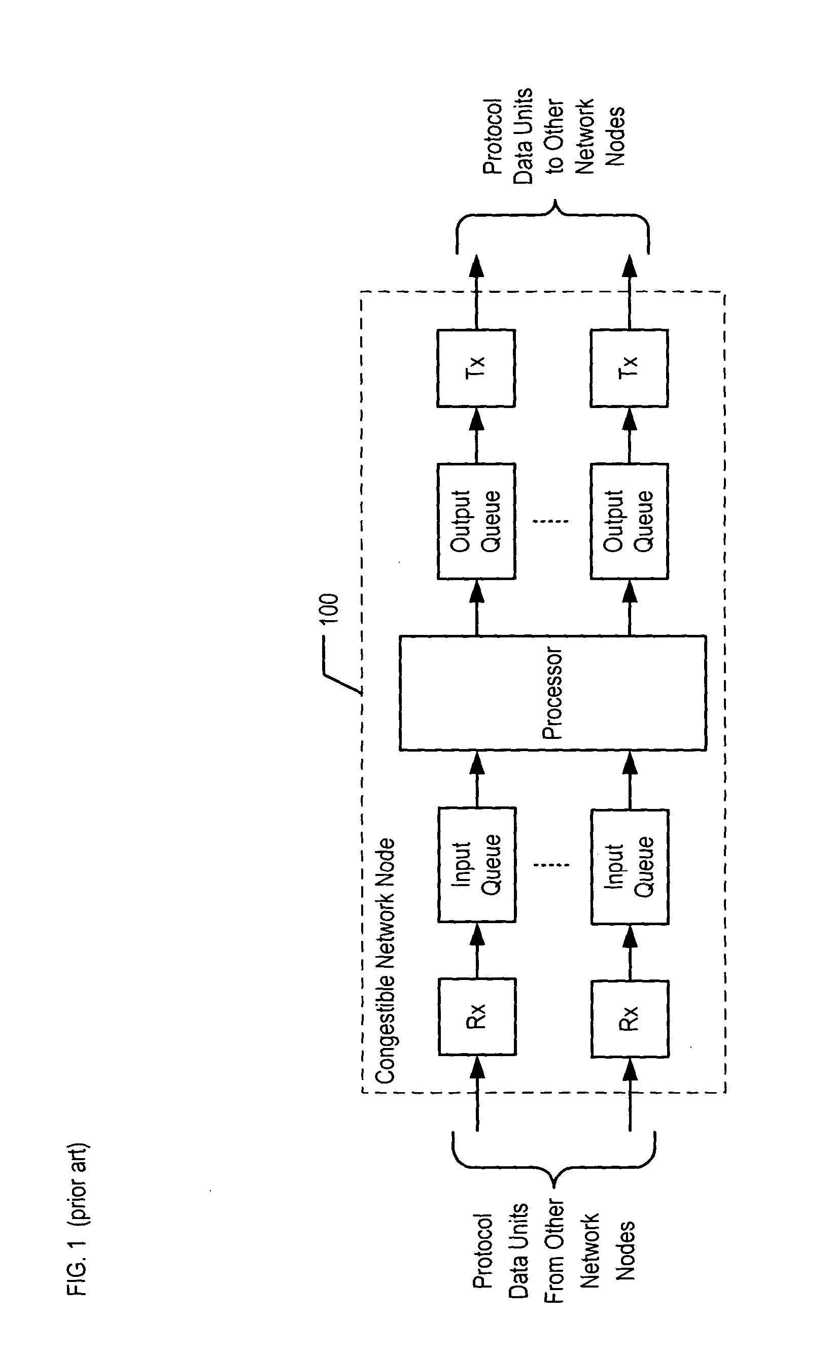
FIELD OF THE INVENTION The present invention relates to telecommunications in general, and, more particularly, to congestion management in telecommunications networks. BACKGROUND OF THE INVENTION In a store-and-forward telecommunications network, each network node passes protocol data units to the next node, in bucket-brigade fashion, until the protocol data units arrive at their final destination. A network node can have a variety of names (e.g. “switch,”“router,”“access point,” etc.) and can perform a variety of functions, but it always has the ability to receive a protocol data unit on one input link and transmit it on one or more output links. FIG. 1 depicts a block diagram of the salient components of a typical network node in the prior art. For the purposes of this specification, a “protocol data unit” is defined as the data object that is exchanged by entities. Typically, a protocol data unit exists at a layer of a multi-layered communication protocol and is exchanged acro...

Claims


Application Information

Patent Timeline
IPC IPC(8): H04L12/28H04L12/56
CPCH04L47/10A01M7/0082A01M7/0085
Inventor GARG, SACHINKAPPES, MARTIN
Owner AVAYA INC
Learn More