Tank system including multiple tanks and control method thereof

Inactive Publication Date: 2005-03-24
TOYOTA JIDOSHA KK
View PDF7 Cites 28 Cited by
  • Summary
  • Abstract
  • Description
  • Claims
  • Application Information

AI Technical Summary

Benefits of technology

[0007] The object of the invention is thus to eliminate the drawbacks of the prior art and to provide a tank system that

Problems solved by technology

In this prior art system including multiple high-pressure tanks with pressure reducing valves, however, it is difficult to individually regulate the release flow rates of the hydrogen gas from the respective high-pressure tanks.
The preferential rele

Method used


Image

  • Tank system including multiple tanks and control method thereof
  • Tank system including multiple tanks and control method thereof
  • Tank system including multiple tanks and control method thereof

Examples


first embodiment

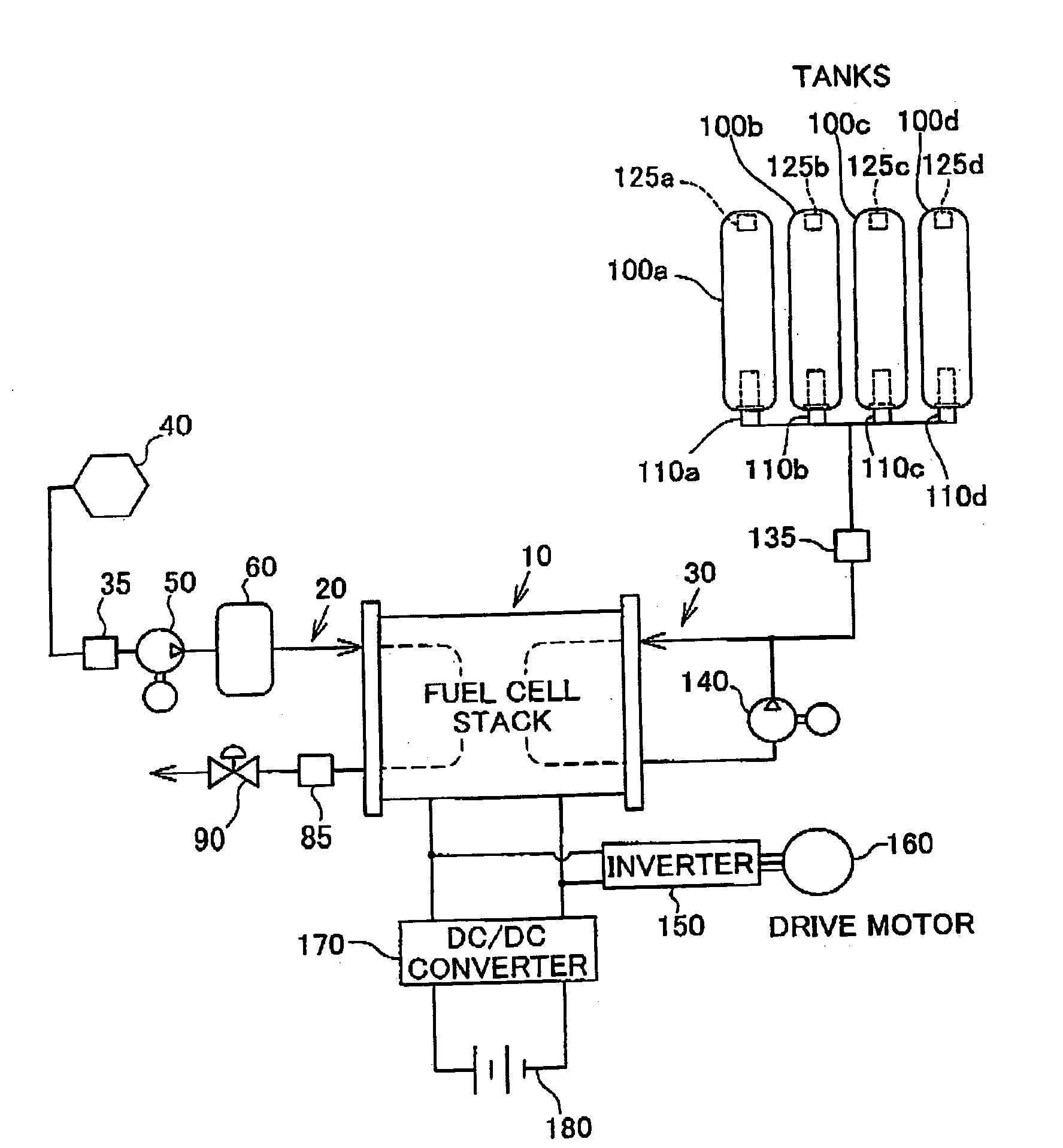
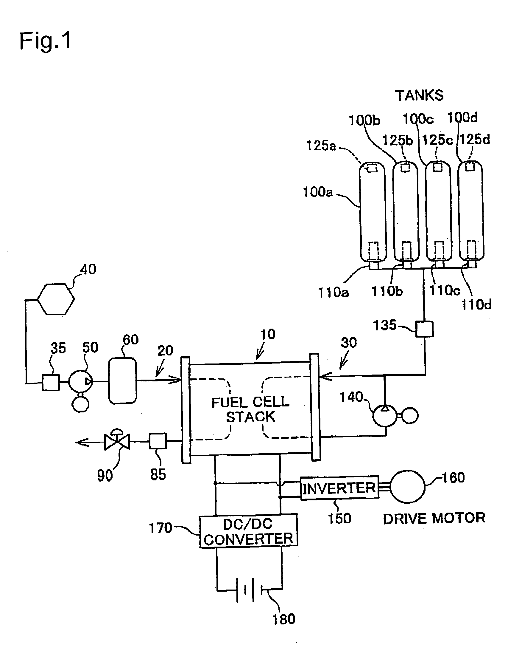
[0034] A fuel cell system with a tank system of the invention is discussed below as a preferred embodiment. FIG. 1 schematically illustrates the configuration of a fuel cell system for the vehicle with a tank system of the invention mounted thereon. The fuel cell system generates electric power through electrochemical reactions of hydrogen with oxygen and uses the generated electric power for a power source of the vehicle. As shown in FIG. 1, the fuel cell system mainly includes a stack of fuel cells or fuel cell stack 10, an air line 20, and a fuel line 30.

[0035] The fuel cell stack 10 is manufactured as a laminate of multiple unit cells, each including a hydrogen electrode (anode) and an oxygen electrode (cathode). The unit cell has a separator, an anode, an electrolyte membrane, a cathode, and another separator laid one upon another in this sequence and generates electric power through electrochemical reactions of hydrogen included in a supply of a fuel gas and oxygen included in...

second embodiment

[0061] As shown in FIG. 5, the tank system of the second embodiment has four hydrogen tanks 100a, 100b, 100c, and 100d. The flowmeter 510 is located in the vicinity of the mouth of each hydrogen tank 100. The flowmeter 510 is a Karman vortex flowmeter that takes advantages of the proportional relation of the flow velocity to the frequency of occurrence of the Karman vortex to measure the flow rate. The flowmeter 510 may be any of other diverse flowmeters including ultrasonic Doppler flowmeters and electromagnetic flowmeters. The measurement values of the flowmeters 510a, 510b, 510c, and 510d are output to the control unit 200 and are used for control of the release flow rates as discussed later.

[0062] The flow control valve set at the mouth of each hydrogen tank 100 is the solenoid valve 500 that excites a solenoid to move a valve plug back and forth and thereby open and close the flow path. The solenoid valve 500 is a normally-closed-type valve, which is initially closed by the pre...


PUM


Abstract

A tank system of the invention with multiple tanks makes a joint flow of a fluid released from the multiple tanks and supplies the joint flow to a downstream device, which is located downstream of the multiple tanks. The tank system includes: primary pressure measurement modules that individually measure internal pressures of the multiple tanks as primary pressures; a secondary pressure measurement module that measures a pressure of the joint flow of the fluid as a secondary pressure; flow rate regulation modules that individually regulate release flow rates of the fluid to be released from the multiple tanks; and a pressure control module that estimates a supply flow rate to be supplied to the downstream device from the measured secondary pressure, and then sets an allocation of the supply flow rate of the fluid to be released from each of the multiple tanks corresponding to the measured primary pressure with regard to the tank. This arrangement ensures adequate regulation of the release flow rates from the multiple tanks.

Description

BACKGROUND OF THE INVENTION [0001] 1. Field of the Invention [0002] The present invention relates to a tank system including multiple tanks and a control method of regulating release flow rates from the multiple tanks in the tank system. [0003] 2. Description of the Related Art [0004] There is conventionally a tank system including multiple tanks for storing high-pressure gases. For example, in a fuel cell system that generates and outputs electric power through electrochemical reactions of hydrogen and oxygen, multiple high-pressure tanks are connected in series for storage of a large quantity of hydrogen gas. In the fuel cell system, the inherent structure of fuel cells requires reduction of the hydrogen gas flowing on the circuit to the low pressure. In a prior art structure, a pressure reducing valve is set in the vicinity of the mouth of each high-pressure tank to significantly reduce the pressure of the hydrogen gas, and the hydrogen gas of the reduced pressure is supplied to ...

Claims


Application Information

Patent Timeline
IPC IPC(8): B60K1/04B60K15/01B60K15/03B60K15/10F17C7/00F17C9/00F17C13/00F17C13/02F17C13/04F17D1/00H01M8/04
CPCF17C13/025F17C2270/0168F17C2270/0184Y02E60/321Y02E60/34F17C2205/0142F17C2205/0146F17C2205/0326F17C2205/0394F17C2221/033F17C2223/0161F17C2223/033F17C2225/0123F17C2225/035F17C2227/0135F17C2250/032F17C2250/0408F17C2250/043F17C2250/0482F17C2250/0495F17C2250/0626F17C2250/0636F17C2265/066F17C2221/012Y02E60/32Y10T137/0396Y10T137/4857Y10T137/6855Y10T137/7761B60K15/01
Inventor KIMBARA, MASAHIKOOGAMI, NOBUYUKIYAMASHITA, AKIRAKOBAYASHI, NOBUO
Owner TOYOTA JIDOSHA KK
Why Eureka
Try Eureka