Methods for stabilizing flow in channels and systems thereof

a channel and flow stabilization technology, applied in the direction of moving conduit heat exchangers, indirect heat exchangers, lighting and heating apparatus, etc., can solve the problems of premature drying out and reduce cooling performance, and overcome the severe oscillation of flow. , the effect of reducing cooling performan

Active Publication Date: 2005-03-24
ROCHESTER INSTITUTE OF TECHNOLOGY
View PDF15 Cites 16 Cited by
  • Summary
  • Abstract
  • Description
  • Claims
  • Application Information

AI Technical Summary

Benefits of technology

The present invention provides a method and system for the efficient removal of the heat potential of flow boiling in a channel or channels, such as microchannels and minichannels. The present invention overcomes the severe oscillatory nature of the flow during flow boiling by initiating the nucleation and flow boiling at specific locations in the channel or channels. The locations are chosen such that the local superheat in the wall and / or surrounding liquid is relatively low and does not lead to the rapid bubble growth that leads to flow and pressure oscillations. Flow and pressure oscillations can lead to flow reversal and premature drying out and to a reduction in cooling performance. To assist in initiating nucleation the present invention heats a region with or immediately preceding a location with nucleation cavities. To provide additional flow stability the present invention may also incorporate local pressure reduction devices.

Problems solved by technology

Flow and pressure oscillations can lead to flow reversal and premature drying out and to a reduction in cooling performance.

Method used


Image

  • Methods for stabilizing flow in channels and systems thereof
  • Methods for stabilizing flow in channels and systems thereof
  • Methods for stabilizing flow in channels and systems thereof

Examples


Embodiment Construction

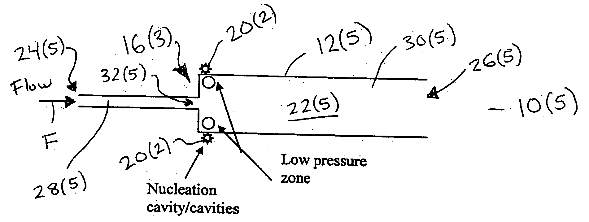
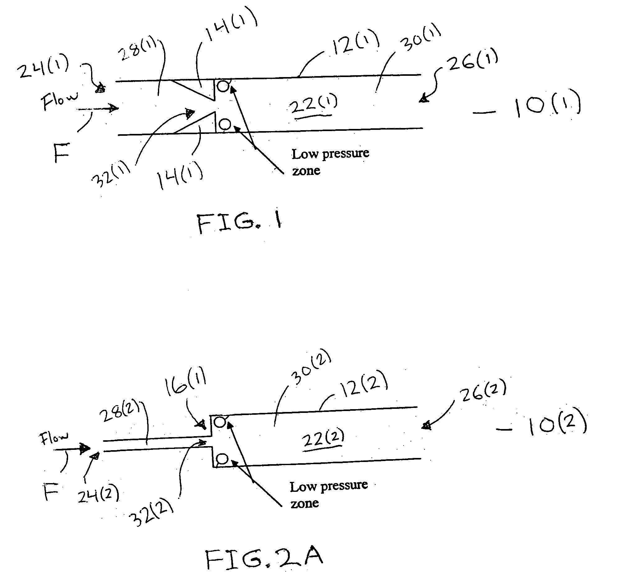
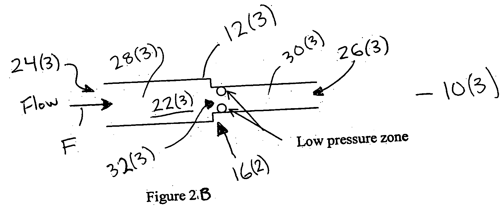
Systems 10(1)-10(10) for stabilizing flow F in one or more channels 12(1)-12(10) in accordance with embodiments of the present invention are illustrated in FIGS. 1-8. The systems 10(1)-10(10) each have a channel 12(1)-12(10) which each includes one or more low pressure devices 14(1)-14(3), low pressure zones 16(1)-16(4), heating device 18(1)-18(2), and / or nucleation cavities 20(1)-20(7), although the systems 10(1)-10(10) each can include other types and numbers of elements arranged in other manners. The present invention provides a number of advantages including providing systems and methods for efficiently removing the heat potential of flow boiling in microchannels and minichannels. The present invention overcomes the severe oscillatory nature of the flow F during flow boiling by initiating the nucleation and flow boiling at specific locations in the channel or channels. The locations are chosen such that the local superheat in the wall of the channel or channels and / or surroundi...


PUM

PropertyMeasurementUnit
hydraulic diameteraaaaaaaaaa
flow boilingaaaaaaaaaa
cross-sectional dimensionaaaaaaaaaa

Abstract

A method and system for stabilizing flow includes introducing a flow into a channel with a minimum cross-sectional dimension of less than three millimeters and triggering a release of one or more bubbles in the flow at one or more locations in the channel. The one or more locations are spaced in from an inlet and an outlet to the channel.

Description

FIELD OF THE INVENTION The present invention generally relates to microchannels and minichannels and, more particularly, to methods and systems for stabilizing flow and / or improving heat transfer performance in microchannels and minichannels and systems thereof. BACKGROUND In a cooling system with a network of multiple parallel microchannels and minichannels, each having a hydraulic diameter less than three mm, a liquid used for cooling is introduced. As the liquid flows through the network, initially heat transfer is by convection from the walls of the microchannels and minichannels. As the liquid flows further downstream through the network, additional heating of the liquid occurs. Eventually, the wall temperature of the microchannels and minichannels rises above the local saturation temperature of the liquid. However, boiling of the liquid does not occur unless there are proper nucleation cavities present. If one or more nucleation cavities are present, nucleation occurs over ...

Claims


Application Information

Patent Timeline
Patent Type & Authority Applications(United States)
IPC IPC(8): F28F13/00F28F13/08F28F13/10
CPCF28F13/00F28F13/08Y10S165/911F28F2260/02F28F13/14F28F13/10
Inventor KANDLIKAR, SATISH G.
Owner ROCHESTER INSTITUTE OF TECHNOLOGY
Why Eureka
Try Eureka