Heat exchanger

a heat exchanger and heat exchanger technology, applied in the field of heat exchangers, can solve the problems of difficult to obtain more space for heat exchanger installation, low heat exchange efficiency, and malfunctions of communication devices

Inactive Publication Date: 2005-03-24
FUJITSU LTD
View PDF14 Cites 45 Cited by
  • Summary
  • Abstract
  • Description
  • Claims
  • Application Information

AI Technical Summary

Benefits of technology

[0015] It is a general object of the present invention to provide a heat exchanger that substantially

Problems solved by technology

Malfunctions in the communication apparatus are caused, particularly, when rain (water) enters the cabinet 100.
Under these circumstances, a heat exchanger with greater thermal efficiency is desired since obtaining more space for installing the heat exchanger is difficult.
However, since the above-described conventional heat exchanger 110 provides low heat exchange effectiveness since the heat exchanger 110 employs a long wave-shaped heat pipe 121 for allowing a cooling medium to flow therethrough.
Although it is possible to improve heat exchange performance by increasing the number of heat exchangers, such increase not only causes difficulty in obtaining installment space

Method used


Image

  • Heat exchanger
  • Heat exchanger
  • Heat exchanger

Examples


Embodiment Construction

[0048] In the following, embodiments of the present invention are described with reference to the accompanying drawings.

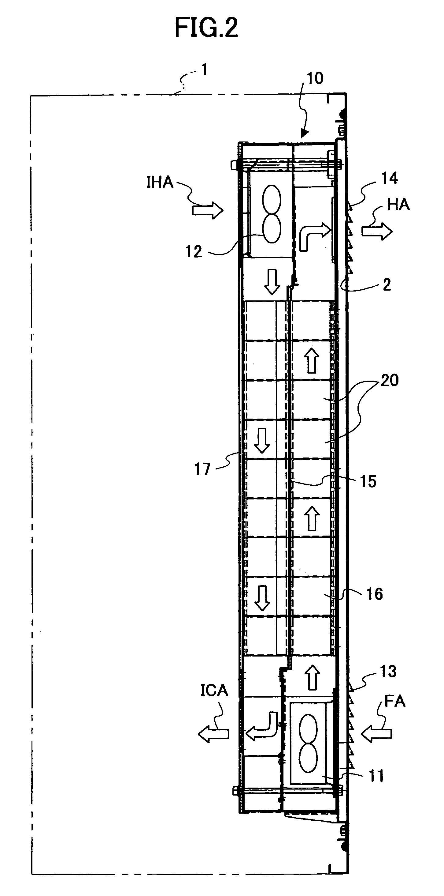
[0049]FIG. 2 is a schematic diagram showing a side part of a cabinet 1 having a heat exchanger 10 according to an embodiment of the present invention.

[0050] The cabinet 1 shown in FIG. 2 is structured for allowing an information processing electronic device unit such as a communication apparatus (not shown) to be installed therein. The cabinet 1 includes a front side door 2. The heat exchanger 10 is disposed with respect to a part of the front side door in the manner illustrated in FIG. 2, for example.

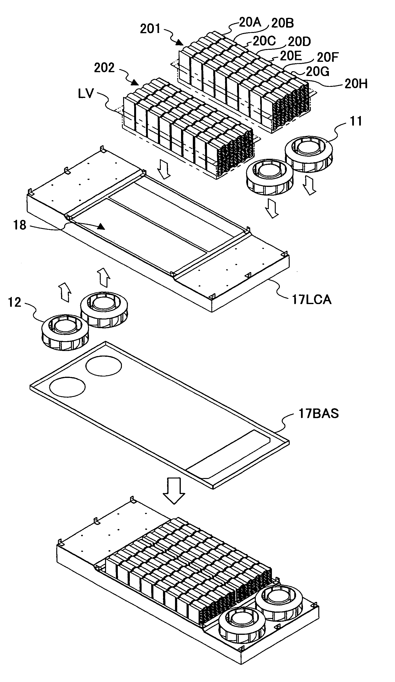
[0051] The heat exchanger 10 has a casing 17 installing therein, for example, a fan 11 for absorbing external air FA via an intake port 13, a heat exchange part 16 for performing heat exchange between the external air FA and the air inside the cabinet 1, and a fan 12 for sending internal high temperature air IHA from the communication apparatus to the heat exchange...


PUM


Abstract

A heat exchanger includes a plurality of unit modules aligned in parallel, in which each unit module has a heat exchange function.

Description

CROSS-REFERENCE TO RELATED APPLICATION [0001] This application is a U.S. continuation application filed under 35 USC 111(a) claiming benefit under 0.35 USC 120 and 365(c) of PCT application JP02 / 06958, filed on Jul. 9, 2002, with the Japanese Patent Office. The foregoing application is hereby incorporated herein by reference. BACKGROUND OF THE INVENTION [0002] 1. Field of the Invention [0003] The present invention generally relates to a heat exchanger for releasing heat from the inside of a casing to the outside. More particularly, a heat exchanger suitably applicable for a cabinet having an information processing electronic device unit such as a communication apparatus that generates large amounts of heat. [0004] 2. Description of the Related Art [0005] In recent years, there has been, for example, an urgent demand for installing next-generation mobile base stations. Along with the growing installment of the next-generation mobile base stations, the demand for outdoor type base sta...

Claims


Application Information

Patent Timeline
IPC IPC(8): F28D15/02H01L23/367H05K7/20
CPCF28D15/0233F28D15/0275H01L23/3672H05K7/206H01L2924/0002H01L2924/00
Inventor HIRAFUJI, KAZUOKOBAYASHI, TOSHIMITSUHASEGAWA, YUUJIMIYAMOTO, MANABU
Owner FUJITSU LTD
Why Eureka
Try Eureka