System and method for forming an underground bore

Inactive Publication Date: 2005-03-24
BAKER HUGHES INC
View PDF17 Cites 26 Cited by
  • Summary
  • Abstract
  • Description
  • Claims
  • Application Information

AI Technical Summary

Benefits of technology

[0013] Examples of the more important features of the invention thus have been summarized rather broadly in order that the detailed description thereof that follows may be better understood, and in order tha

Problems solved by technology

The large flow volumes result in a substantial amount of particulate matter being deposited.
However, environmentally sensitive structures, such as coral reefs, may be damaged by the deposition of large amounts of such material.
Use of such a wireline tool prevents the use of a rotary drilling system.
The limits of the prior art techniques are caused by the friction induced drag of the drill pipe as it lays against the wall of the pilot hole.
In addition, the relatively flexible drill pipe tends to buckle as the thrust load is increased, exacerbating the problem.

Method used


Image

  • System and method for forming an underground bore
  • System and method for forming an underground bore
  • System and method for forming an underground bore

Examples


Embodiment Construction

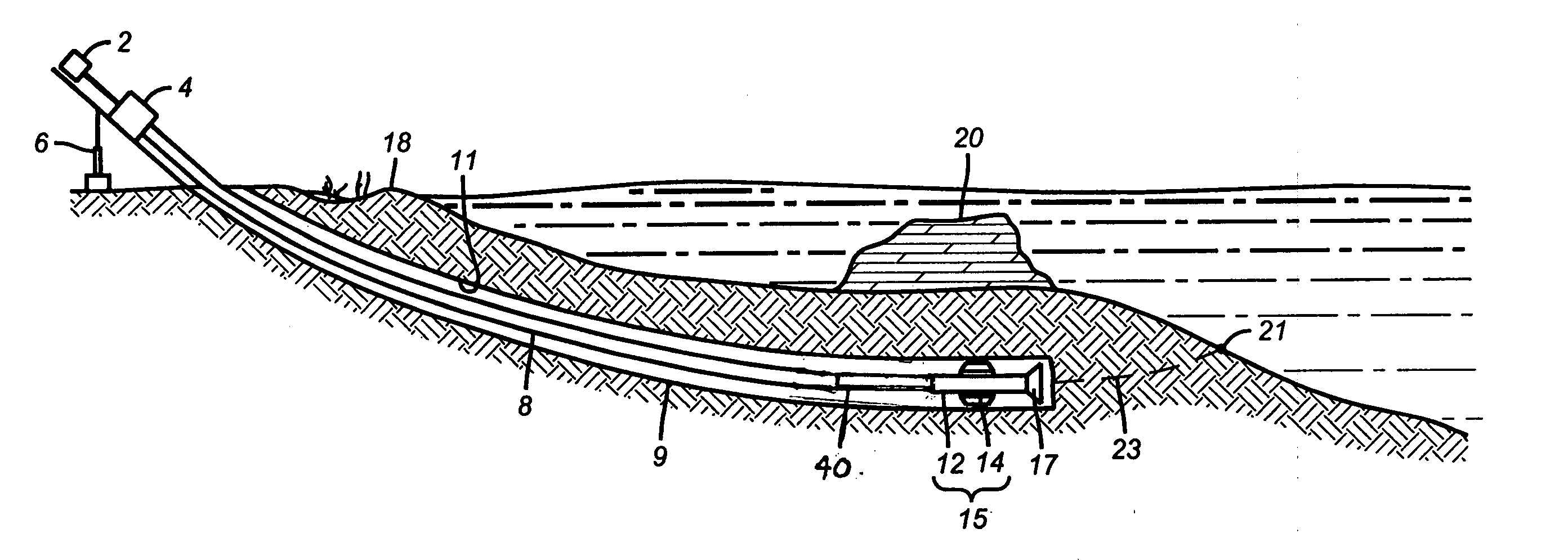
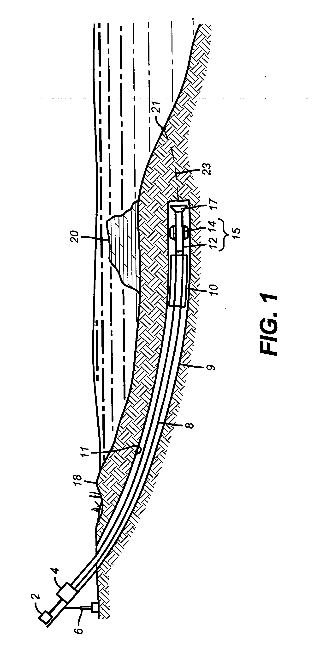
[0019] The drilling rig being used for horizontal directional drilling, according to one embodiment, is a ramp style rig shown schematically at 1 in FIG. 1. The rig is mounted onshore and removed back from the environmentally sensitive beach area 18. Located on the seabed, and at a distance offshore, is an environmentally sensitive structure 20 such as a coral reef. The borehole 9 is intended to travel under the beach 18 and the reef 20 and to exit at a suitable predetermined distance at location 21.

[0020] Referring to drilling rig 1, the ramp serves the same purpose as a derrick on a standard vertical drilling rig. The ramp may be elevated at one end by means of a pivoting leg system 6 to raise the ramp to a predetermined angle from the horizontal. The rig includes a rotary table 4 and a thruster 2. The rotary table is driven by hydraulic or electric motors. A mud pumping system (not shown) is skid mounted adjacent the ramp and utilizes suitable pumps to operate the mud system. Wh...


PUM


Abstract

A system for drilling a substantially horizontal borehole, comprises a rotating drill string extending from a surface system to a location in the horizontal borehole, the drill string having a drill bit at a bottom end. A rotary steerable system in the drill string proximate the drill bit is adapted to direct the rotating drill string toward a desired exit point. In another aspect, a method for drilling a substantially horizontal borehole from a surface location to an offshore exit location, comprises drilling a borehole using a rotary steerable system to direct the borehole along a predetermined trajectory toward the exit location. The borehole is reamed from the surface location toward the exit location while recovering a drilling fluid at the surface location.

Description

CROSS REFERENCE TO RELATED APPLICATIONS [0001] This application claims the benefit of U.S. application Ser. No. 60 / 468,221 filed on May 5, 2003.STATEMENT REGARDING FEDERALLY SPONSORED RESEARCH OR DEVELOPMENT [0002] Not Applicable BACKGROUND OF THE INVENTION [0003] 1. Field of the Invention [0004] The present invention relates to systems and methods for horizontal directional drilling and more particularly to the use of a self-controlled, rotary steerable system for use in horizontal direction drilling. [0005] 2. Description of the Related Art [0006] Horizontal directional drilling is the application of drilling techniques to steer a drill along a prescribed pathway beneath an obstacle such as a river or beach. This pathway is then enlarged and improved such that a pipeline or conduit can be installed beneath the obstacle. The drill path takes a line below the surface to avoid disturbance of the banks or beach and thereby greatly reduces environmental impact. Commonly, the drill path...

Claims


Application Information

Patent Timeline
IPC IPC(8): E21B7/06E21B7/28E21B44/00
CPCE21B7/068E21B44/005E21B7/28
Inventor EVANS, NIGELBRUDERER, MARC
Owner BAKER HUGHES INC
Why Eureka
Try Eureka