
Pump, pump for liquid chromatography, and liquid chromatography apparatus

a liquid chromatography and pump technology, applied in the direction of machines/engines, settling tank feed/discharge, chemical/physical processes, etc., can solve the problem of reducing the speed reduction ratio of the motor, the liquid cannot be sent at a large flow rate, and the plunger is decreased. the effect of short tim

Inactive Publication Date: 2005-03-24
HITACHI HIGH-TECH CORP
View PDF15 Cites 125 Cited by
  • Summary
  • Abstract
  • Description
  • Claims
  • Application Information

AI Technical Summary

Benefits of technology

The present invention provides a pump for liquid chromatography that can feed liquid at an extremely low flow rate and complete filling eluate or discharging bubbles at the startup of test in a short time. The pump includes a cylinder and a plunger that reciprocates in the cylinder and sucks and discharges fluid, and an actuator that directly drives the plunger. The actuator has a function for detecting load applied to the plunger or selectively switches means for driving the plunger based on the flow rate of liquid. The pump is particularly useful for a flow rate of liquid ranging from 0.1 nL / min to (50 μL / min. The invention is constructed in such a way that a small pump feeds eluate at an extremely low flow rate and that a large pump fills the eluate and discharges bubbles at the startup of test.

Problems solved by technology

However, in the above-described conventional pump for liquid chromatography, in a case where in order to feed liquid at an extremely low flow rate, the speed reduction ratio of a motor is increased to decrease the speed of the plunger or the diameter or stroke of the plunger is decreased, conversely, the liquid can not be sent at a large flow rate.
For this reason, this pump presents a problem that it takes much time to fill eluate into the passage of a measurement system on the downstream side of the pump and a problem that bubbles remaining in the pump can not be easily discharged.
When the bubbles can not be discharged, even if the plunger reciprocates, the plunger only compresses or expands the bubbles and cannot discharge the liquid.
Therefore, there is presented a problem that this pump is not appropriate for constructing a pump used for an extremely low flow rate.

Method used


Image

  • Pump, pump for liquid chromatography, and liquid chromatography apparatus
  • Pump, pump for liquid chromatography, and liquid chromatography apparatus
  • Pump, pump for liquid chromatography, and liquid chromatography apparatus

Examples


Embodiment Construction

[0023] The embodiments of the invention will be described with reference to the drawings.

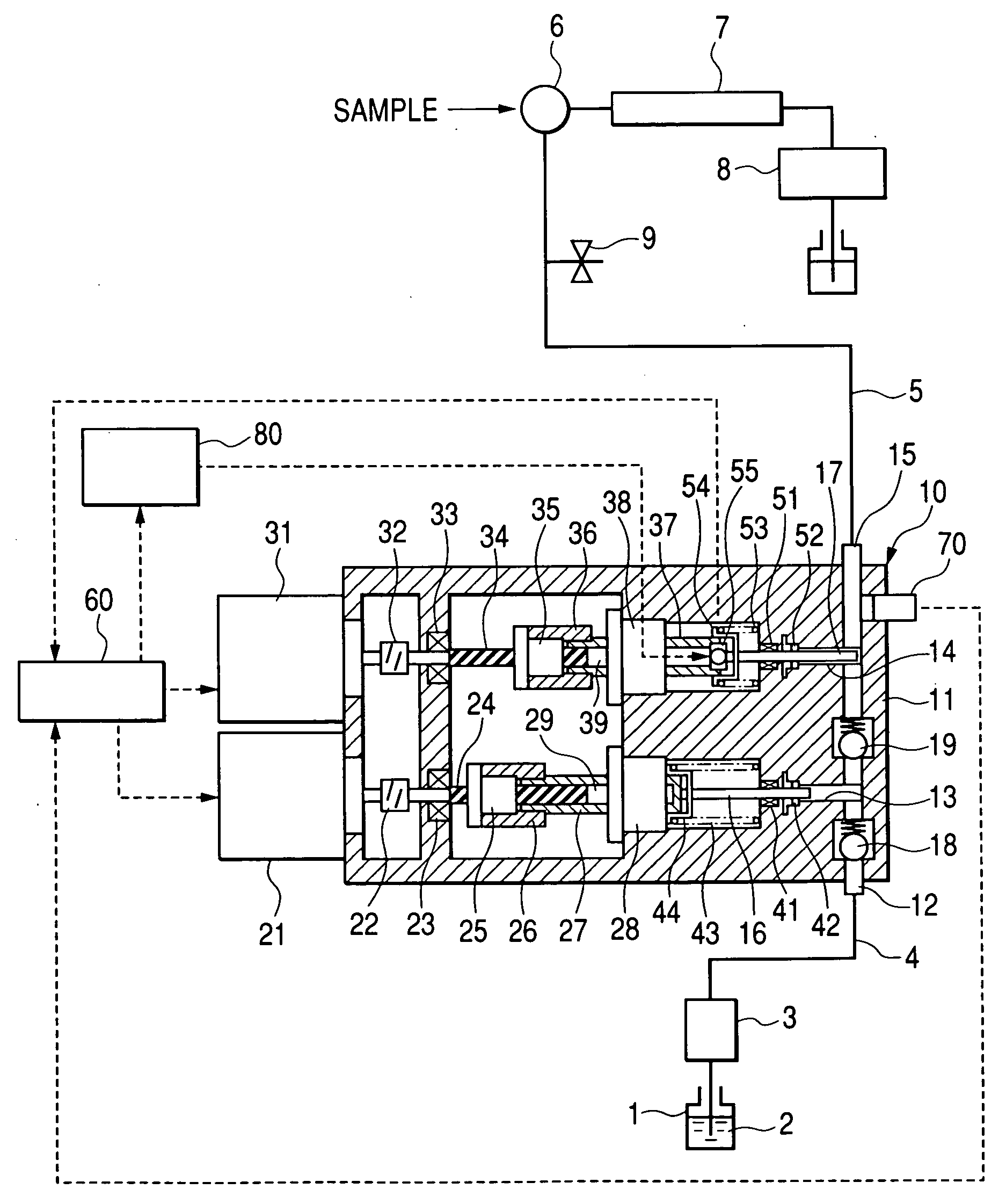
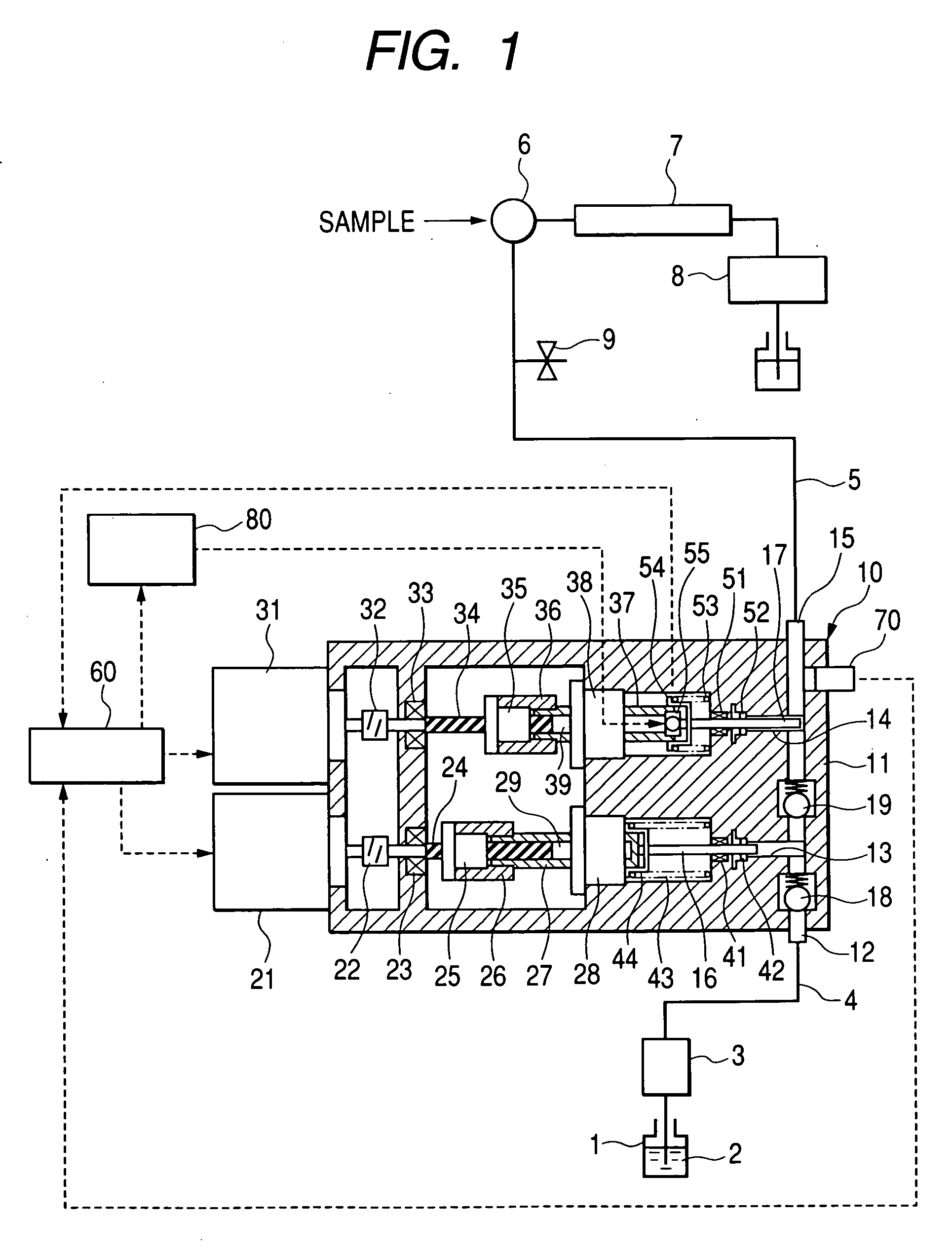
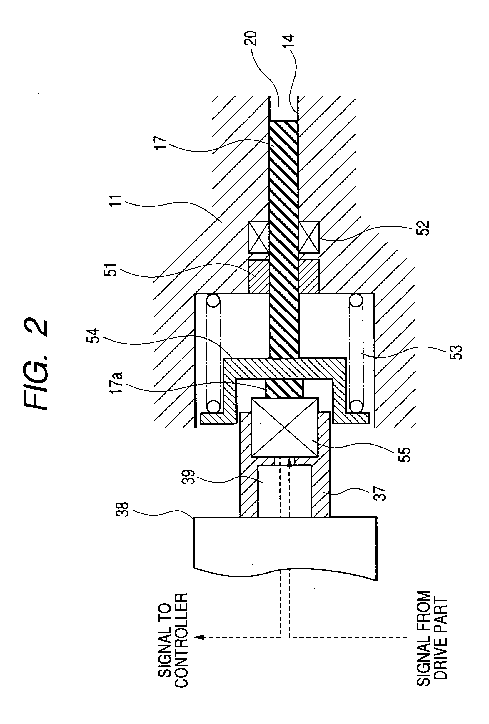
[0024]FIG. 1 is the hydraulic circuit to show the general construction of a system for feeding liquid of liquid chromatography to which a pump for liquid chromatography of the invention is applied. FIG. 2 is an enlarged sectional view to show the schematic structure of a pump body of the pump for liquid chromatography of the invention. FIG. 3 is a chart to show the flow rate range of the pump. FIG. 4 is a chart to show one example of a method for driving the pump for liquid chromatography.

[0025] In FIG. 1 and FIG. 2, a system for feeding liquid has a pump 10 used for liquid chromatography that sucks and pressurizes eluate 2 in an eluate storing container 1 via a degasser 3 and a suction piping 4; an injector 6 that discharges the eluate from the pump 10 used for liquid chromatography and has a sample to be analyzed injected thereto via a discharge piping 5; a column 7 filled with fine silica g...


PUM

PropertyMeasurementUnit
flow rateaaaaaaaaaa
voltageaaaaaaaaaa
flow rateaaaaaaaaaa

Abstract

The invention provides a pump for liquid chromatography excellent in feeding liquid stably at an extremely low flow rate and in discharging bubbles at startup. In a pump for liquid chromatography including a cylinder and a plunger that reciprocates in the cylinder to suck and discharge fluid, the pump further includes a large-flow-rate pump that feeds liquid by the plunger, a small-flow-rate pump that feeds the liquid by the plunger, motion conversion means that converts the rotational motion of a motor to a reciprocating motion, an actuator that directly drives the plunger, and a drive part that drives the actuator, and selectively switches means for driving the plunger.

Description

CLAIM OF PRIORITY [0001] The present application claims priority from Japanese application serial JP 2003-326806 filed on Sep. 18, 2003, the content of which is hereby incorporated by reference into this application. FIELD OF THE INVENTION [0002] The present invention relates to a pump excellent in feeding liquid stably at an extremely low flow rate and in discharging bubbles at startup. Particularly, the invention relates to a pump for liquid chromatography excellent in feeding liquid stably at an extremely low flow rate and in discharging bubbles at startup. BACKGROUND OF THE INVENTION [0003] A conventional pump for liquid chromatography generally has a construction in which eluate is sucked and discharged by a plunger reciprocating in a cylinder and a construction has been known in which a first plunger and a second plunger are independently driven by a motor to reduce a pulsating flow rate by driving both of the plungers cooperatively. One example of this construction is disclos...

Claims


Application Information

Patent Timeline
Patent Type & Authority Applications(United States)
IPC IPC(8): F04B9/00F04B9/02F04B11/00F04B17/03F04B23/06F04B49/00F04B49/10F04B53/10G01N30/32
CPCF04B9/02F04B11/0058G01N2030/326G01N30/32F04B17/03
Inventor TAKAO, KUNIHIKOKAJI, HIRONORIITO, MASAHITO
Owner HITACHI HIGH-TECH CORP
Learn More