Laser range finder

a laser range finder and laser range technology, applied in the direction of conveyors, distance measurement, instruments, etc., can solve the problems of large positional error, inability to meet satellite inter-satellite ranging, and inability to meet satellite ranging needs, etc., to achieve the effect of accurately measuring the inter-satellite rang

Inactive Publication Date: 2005-03-24
NEC CORP
View PDF1 Cites 30 Cited by
  • Summary
  • Abstract
  • Description
  • Claims
  • Application Information

AI Technical Summary

Benefits of technology

[0012] It is therefore an object of the present invention to provide a small-size laser range finder which is capable of measuring the inter-satellite range sufficiently accurately in real-time.

Problems solved by technology

However, the conventional laser range finder suffers the following problems:
Therefore, the conventional reflected beam reception process is not suitable for use on satellites for inter-satellite ranging.
The positional information that is sent from the ground to a satellite for tracking a moving satellite to point the laser beam suffers a large positional error and is not in real-time.
Therefore, the positional information from the ground is not sufficient for use on the laser range finder on the satellite for tracking the target.
Another problem is that laser range finders on satellites have their laser oscillators tending to cause a misalignment due to harsh environmental changes in space, and hence have a reduced laser output capability.
Because of the various factors described above, it is difficult for the conventional laser range finder to measure the inter-satellite range sufficiently accurately in real-time.

Method used


Image

  • Laser range finder
  • Laser range finder
  • Laser range finder

Examples


Embodiment Construction

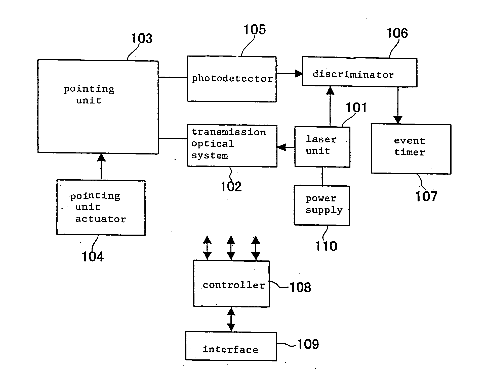
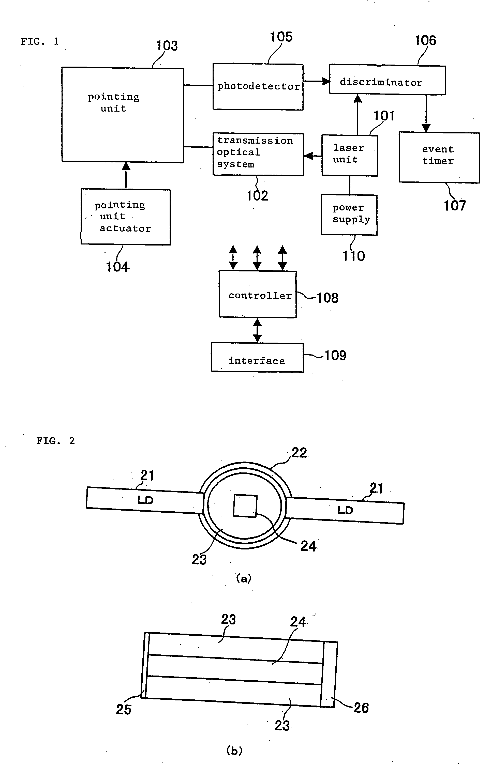
[0021]FIG. 1 shows in block form a laser range finder according to an embodiment of the present invention. As shown in FIG. 1, the laser range finder comprises laser unit 101, transmission optical system 102, pointing unit 103, pointing unit actuator 104, photodetector 105, discriminator 106, event timer 107, controller 108, interface 109, and power supply 110.

[0022] Laser unit 101 comprises a monolithic laser oscillator for emitting a short-pulse laser beam. The monolithic laser oscillator is a passive Q switch employing, as a saturable absorber, a Cr4+-doped YAG (Yttrium Aluminum Garnet) (Cr4+:YAG) crystal.

[0023] FIGS. 2(a) and 2(b) show structural details of the monolithic laser oscillator. As shown in FIGS. 2(a) and 2(b), the monolithic laser oscillator has non-doped YAG 23 disposed in light collection tube 22 having an inner layer of BaSO4, and Nd YAG crystal 24 as a laser medium disposed in non-doped YAG 23. Nd YAG crystal 24 has a size of 3″×10 mm.

[0024] One end 25 of ligh...


PUM


Abstract

A laser range finder measures the range between itself and another laser range finder by propagating a laser beam only in one way therebetween. A laser unit generates a short-pulse laser beam to be transmitted to the other laser range finder. A photodetector receives a short-pulse laser beam transmitted from the other laser range finder and detects the direction of the other laser range finder. A pointing unit adjusts the direction in which the laser beam generated by the laser unit is to be transmitted, into alignment with the direction of the other laser range finder which is detected by the photodetector. A controller stores in advance a holding time after the other laser range finder receives the short-pulse laser until the other laser range finder transmits the short-pulse laser, and calculates the range between the own laser range finder and the other laser range finder from the time at which the short-pulse laser beam is transmitted, the time at which the short-pulse laser beam is received, and the holding time.

Description

BACKGROUND OF THE INVENTION [0001] 1. Field of the Invention [0002] The present invention relates to an apparatus for laser ranging, and more particularly to a laser range finder for use on a satellite for inter-satellite ranging. [0003] 2. Description of the Related Art [0004] For accurate inter-satellite time synchronization, it is necessary to accurately measure the inter-satellite range, which runs up to 70,000 km. [0005] One apparatus for accurately measuring long ranges is a laser range finder using short-pulse laser (see, for example, Japanese laid-open patent publication No. 10-239600). The conventional laser range finder emits a short-pulse laser beam toward a target and detects the laser beam reflected from the target to measure the distance up to the target. This range-finding process will be hereafter referred to as a reflected beam reception process. [0006] If a moving object such as a satellite is a target, then the laser range finder directs the laser beam toward the ...

Claims


Application Information

Patent Timeline
Patent Type & Authority Applications(United States)
IPC IPC(8): G01C3/06B64G1/36B64G1/64G01S3/784G01S7/497G01S17/10G01S17/42G01S17/74
CPCB64G1/36B64G1/646G01S17/74G01S7/4972G01S17/10G01S3/784
Inventor KASE, TEIJI
Owner NEC CORP
Why Eureka
Try Eureka