

Vehicle frame having air tank cross member
a cross-member and vehicle frame technology, applied in the direction of interconnection systems, vehicle components, resilient suspensions, etc., can solve the problems of affecting the performance of the vehicle, and occupying valuable space, so as to improve the structural integrity, reduce weight, and simplify the structure
- Summary
- Abstract
- Description
- Claims
- Application Information
AI Technical Summary
Benefits of technology
Problems solved by technology
Method used
Image

Examples
first embodiment
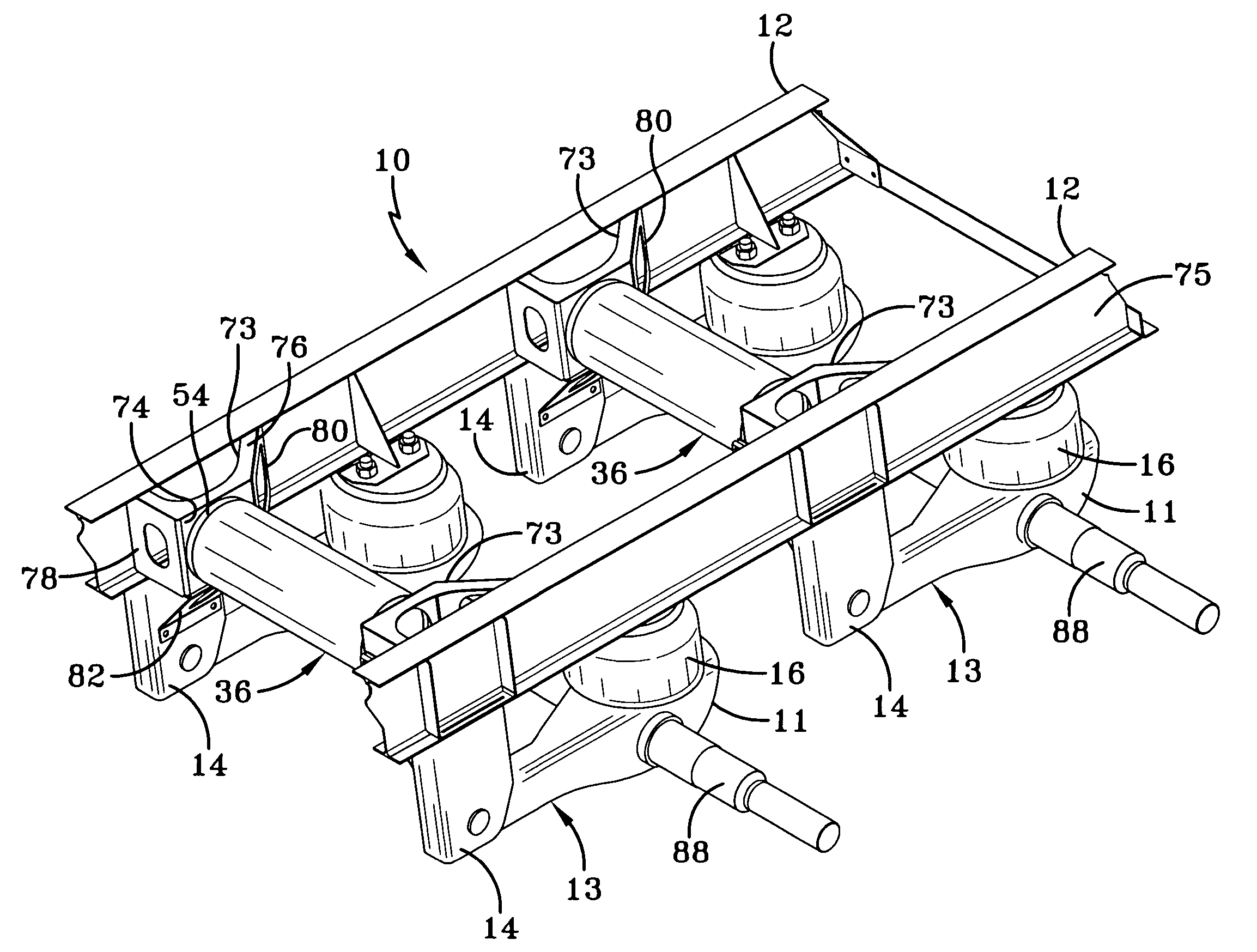
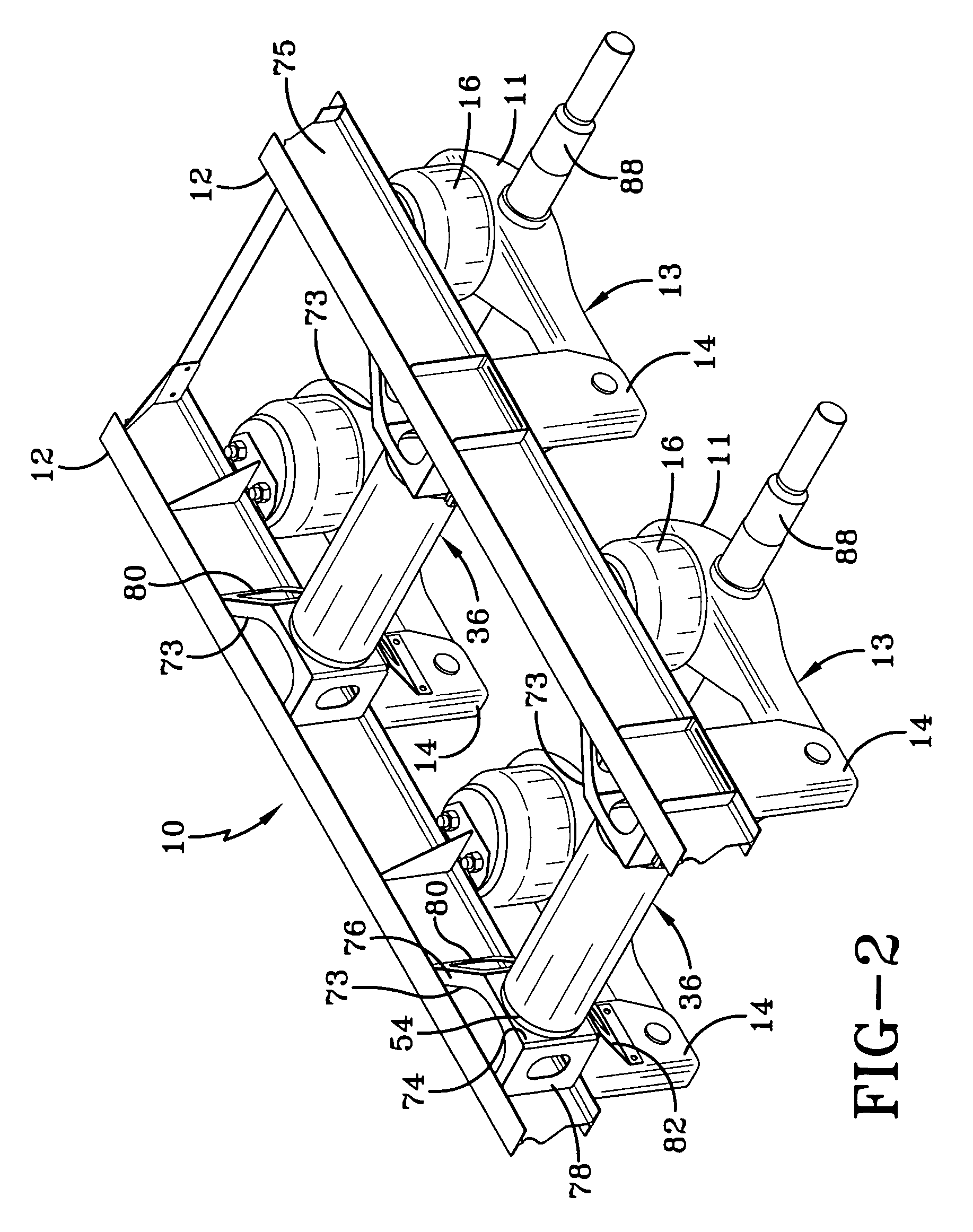
[0027] With reference now to FIG. 2 of the drawings, it can be seen that a primary frame in accordance with the present invention is designated generally by the numeral 10. More particularly, frame 10 includes a pair of spaced-apart, parallel, elongated, and longitudinally-extending main members 12. Each main member 12 has a suspension hanger bracket 14 mounted on and extending downwardly therefrom to pivotally receive a trailing arm beam 11 of an air suspension assembly 13 in a well-known manner. An air spring 16 extends between and is attached to its respective main member 12 and the rear end of its respective beam 11 to complete the main components of suspension assembly 13. An axle 88 is captured in beams 11 of each pair of suspension assemblies 13 to complete an axle / suspension system. It is understood that additional pairs of suspension assemblies 13 (only one additional pair shown) are each mounted in an identical manner at longitudinally spaced locations beneath frame 10 for...
second embodiment
[0034] the frame of the present invention is shown in FIGS. 6 and 7 and is indicated generally at 17. A bracket 18, preferably formed of a sturdy material such as metal, is mounted on the inboard surface of each main member 12 (only one shown) and hanger 14 by any suitable means such as welds or fasteners. As shown in FIGS. 6 and 7, mounting bracket 18 has a generally cupped or curvate shape. A cylindrical-shaped air tank 20, which is yet another design of a vessel in addition to tanks 36 and 90 shown in FIGS. 4 and 5, respectively, is secured between opposed mounting brackets 18 by a continuous weld (not shown) extending about the entire interface 22 of each of the cylindrical ends of tank 20 and its respective mounting bracket 18. The welds at each interface 22 provide an airtight closure to tank 20, it being understood that each bracket 18 also functions as an end cap or closure 24 at its respective end of tank 20.
[0035] It thus clearly can be seen by referring to FIGS. 6 and 7 a...
fourth embodiment
[0041] Referring now to FIG. 9, a fourth embodiment frame of the invention is designated generally by the numeral 60. In this embodiment of a frame of the present invention, mounting brackets 62 preferably are fabricated from metal and are attached to opposed main members 12 (only one shown) as by welding or the like. Mounting rings 54 at opposite ends of air tank 36 each are received by a collar 70 formed on the inboard end of each mounting bracket 62 and may be secured thereto by welding, rivets or other appropriate fastening means (not shown). Extending angularly and outboardly from collar 70 to main member 12 are a plurality of webs or flanges 64, 66, 68 which are welded, bolted or riveted (not shown) at their outboardmost ends to main member 12. Webs 64, 66, 68 form a triangulated mounting base adapted to react and withstand the various vehicle operation forces imparted thereto by virtue of interconnection with air tank 36 serving as a rigid subframe cross member between the pa...
PUM
 Abstract
Description
Claims
Application Information