
Heat/electric power supply system having power storage unit

a technology power storage unit, which is applied in the direction of emergency power supply arrangement, electric generator control, machines/engines, etc., can solve the problems of insufficient absoluteness for the wider range spread of heat/electric power supply system, and achieve the effect of reducing equipment costs, increasing the range spread of heat/electric power supply system, and saving spa

Inactive Publication Date: 2005-03-24
CHO TONG RAE +1
View PDF19 Cites 66 Cited by
  • Summary
  • Abstract
  • Description
  • Claims
  • Application Information

AI Technical Summary

Benefits of technology

[0035] Moreover, since the output of a generator is equalized by operating a generator also in a night time zone, and storing electric power in a power storage unit, operation efficiency of a heat / electric power supply system is good.
[0046] On the other hand, since miniaturization was pursued ultimately, it became being able to attain the cost cut of equipment, and a saving of space (equipment installation performance).
[0047] A possibility of the wider range spread of heat / electric power supply systems increased.
[0049] Thereby, it is expectable that a power storage unit can have the effect of leading to the cut of the whole commercial electric power in a peak time zone also as the whole state, by achieving the same function as the reservoir of the pumped hydro power generation, and using commercial electric power stored in the night time zone in a peak time zone.
[0085] Spreading especially this system broadly by attaining miniaturization low-cost-ization is called for.
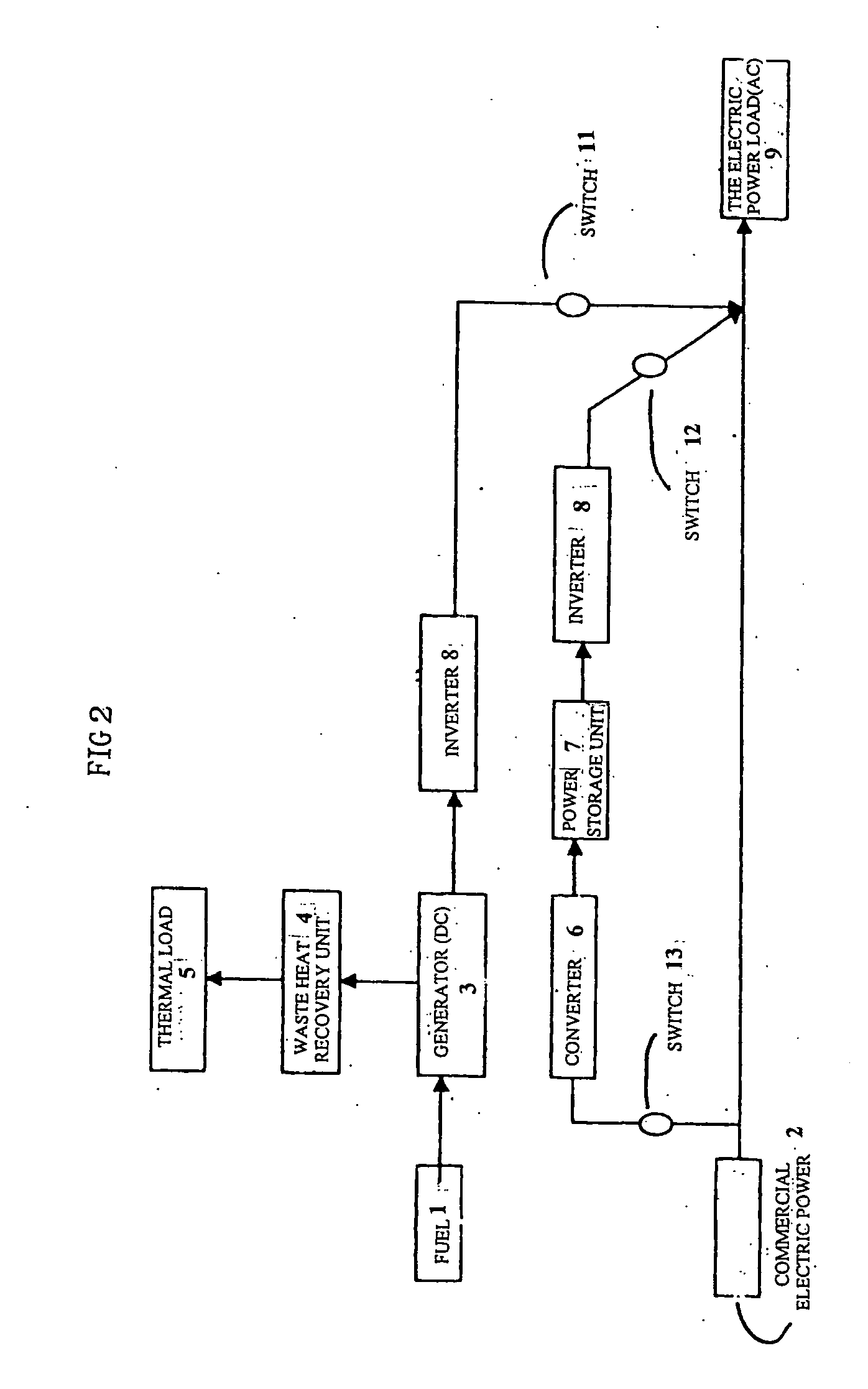
[0110] Moreover, in the case of the electric power load of direct current, it becomes unnecessary (the inverter installed in the slipstream side of a power storage unit), and the system is simplified.

Problems solved by technology

That is, as for a back-up type heat / electric power supply system, although an electric industry company also had a merit that some commercial electric power was used in the evening charge time zone, it was inadequate absolutely for the wider range spread of heat / electric power supply systems.

Method used


Image

  • Heat/electric power supply system having power storage unit
  • Heat/electric power supply system having power storage unit
  • Heat/electric power supply system having power storage unit

Examples


Embodiment Construction

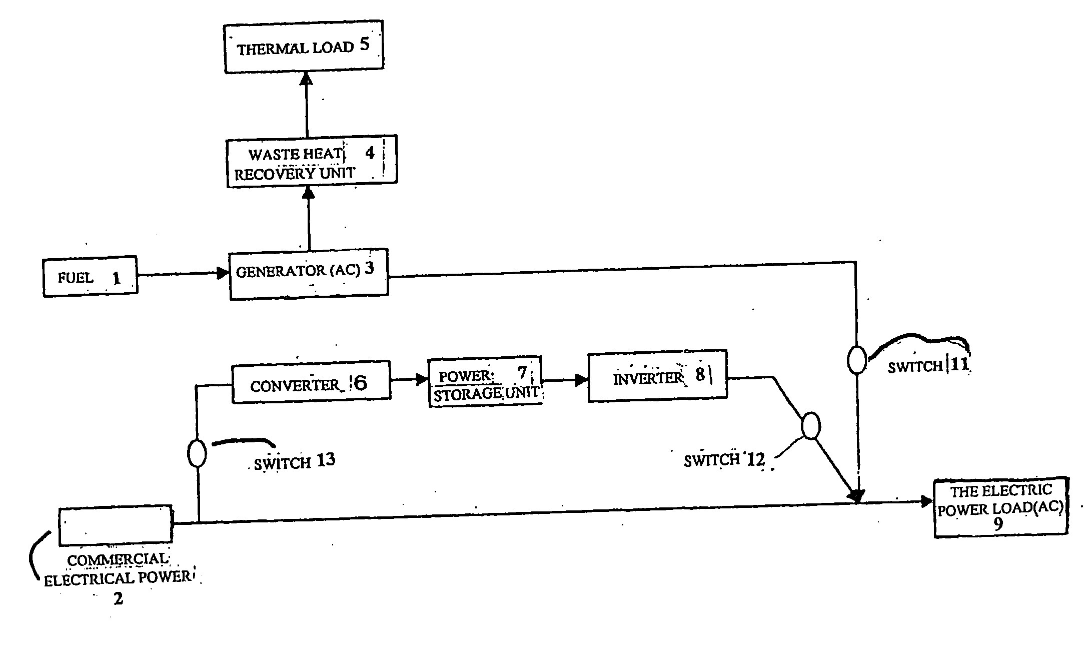
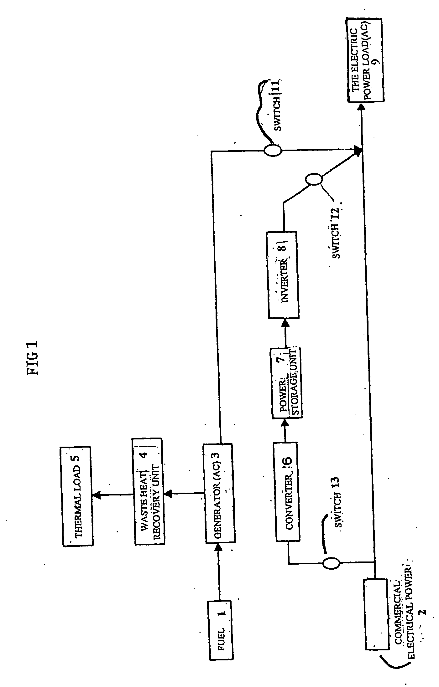
[0143] First, the case (refer to FIG. 1) of the electric power load of alternative-current and the generator of alternative-current is explained as an embodiment.

[0144]FIG. 1 is a block diagram of the 1st embodiment of the present invention (when the generator 3 is alternative-current and the electric power load 9 is alternative-current).

[0145] This heat / electric power supply system 100 of FIG. 1 contains the generator 3, the power storage unit 7 of alternative-current, and the waste heat recovery unit 4.

[0146] Electric power (in the case of alternative-current electric power, the voltage and frequency are substantially the same as those of commercial electric power 2, for example, they are 100V and 60 Hz.) generated by the generator 3 is supplied to the electric power load 9.

[0147] Fuel 1 is supplied to the generator 3.

[0148] Waste heat from the generator 3 is collected by the waste heat recovery unit 4, and, collected heat is supplied to the heat load 5 (as heat sources, such...


PUM


Abstract

A heat / electric supply system the entire efficiency of which is enhanced while reducing the capacity of facility. The heat / electric supply system is characterized in that electric power is supplied from a generator, a commercial power supply and a power storage unit in the time zone when power consumption by the power load is higher than a specified output C1 and commercial power is stored in a power storage unit in the night time zone can be utilized at the time of peak power demand, the backup power at the time of peak power demand can be reduced.

Description

FIELD OF THE INVENTION [0001] The present invention relates to a heat / electric power supply system (it is also called a cogeneration system.) which supplies heat and electric power. BACKGROUND ART [0002] A heat / electric power supply system attracts attention recently as a system which uses effectively waste heat generated on the occasion of power generation. [0003] Since heat is also effectively used by waste-heat recovery with electric power from a generator in a heat / electric power supply system, the use efficiency of energy is high. [0004] In recent years, introduction of an electric power supply system of an independent form is considered. [0005] This is because it was admitted with deregulation of Electric Utility Law that entrepreneurs other than a general electric industry company entered into the electric industry. [0006] A specific point supply where the area to which supplies electricity is limited is mentioned as an entry form to such the electric industry. [0007] In such...

Claims


Application Information

Patent Timeline
IPC IPC(8): H02J3/32F02C6/00H01M8/00H02J3/28H02J3/38H02J7/34H02J9/06H02P9/04
CPCH02J3/28Y02E20/14H02J9/066H02J3/32Y02P90/50F02C6/00
Inventor CHO, TONG-RAESATO, SOICHI
Owner CHO TONG RAE
Learn More