High-efficiency amplifier, converter and methods

a converter and high-efficiency technology, applied in the direction of amplifiers, dc amplifiers with modulator-demodulator, semiconductor devices/discharge tubes, etc., can solve the problems of significant capital and operational expenses of power amplifiers, inability to support the power levels and input bandwidths required for rf applications, and two-level quantizers significantly limit achievable performance in terms of output noise level, signal-to-noise ratio (snr) and dynamic range, so as to reduce effect

Inactive Publication Date: 2005-03-24
MICROSOFT TECH LICENSING LLC
View PDF3 Cites 25 Cited by
  • Summary
  • Abstract
  • Description
  • Claims
  • Application Information

AI Technical Summary

Benefits of technology

[0024] A method according to another broad aspect of the invention includes decomposing an input signal into a plurality of two state signals, each two state signal having a respective on level and off level, and adjusting the two state signals to reduce effects of a subsequent processing operation, to thereby produce at least one adjusted phase signal.

Problems solved by technology

Power amplifiers account for a significant portion of the capital and operational expense in current wireless base station designs.
However, these architectures typically consist of a single phase and are not capable of supporting the power levels and input bandwidths required for RF applications.
Although two level quantizers possess desirable features of simplicity and inherent linearity, a two level quantizer significantly limits achievable performance in terms of loop stability, output noise level, signal-to-noise ratio (SNR) and dynamic range.
This leads to significant complications and limitations in the development of high performance, high frequency, multi-bit Sigma-Delta digital to analog converters.
Additionally, the multi-level analog output limits the applications of the converters.
This limits the application of Sigma-Delta modulators to single bit quantizers.
Other approaches attempt to address the issues surrounding multi-bit linearity in the output stage in Sigma-Delta DACs, but similarly fail to overcome the above limitations.

Method used


Image

  • High-efficiency amplifier, converter and methods
  • High-efficiency amplifier, converter and methods
  • High-efficiency amplifier, converter and methods

Examples


Embodiment Construction

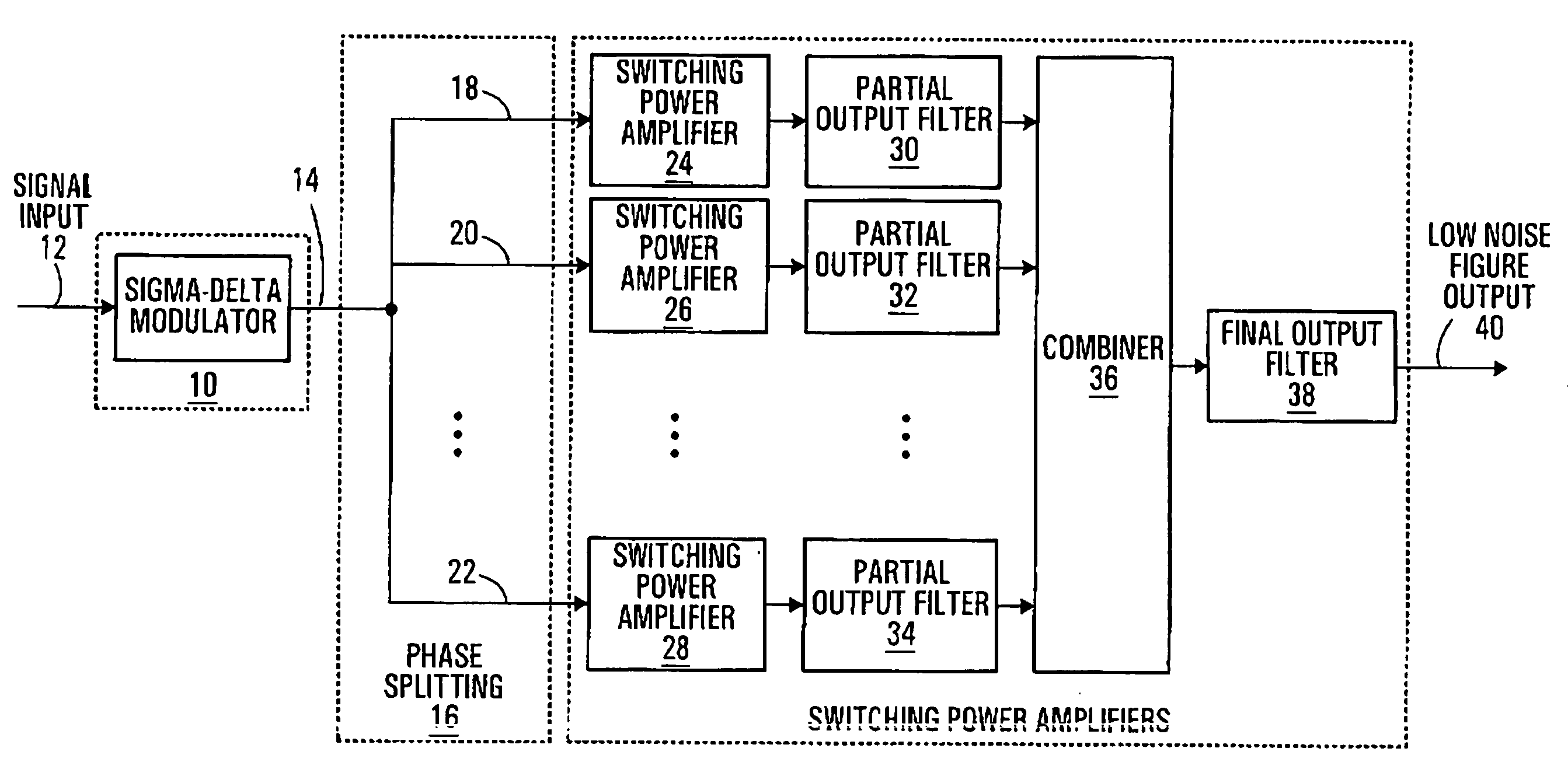
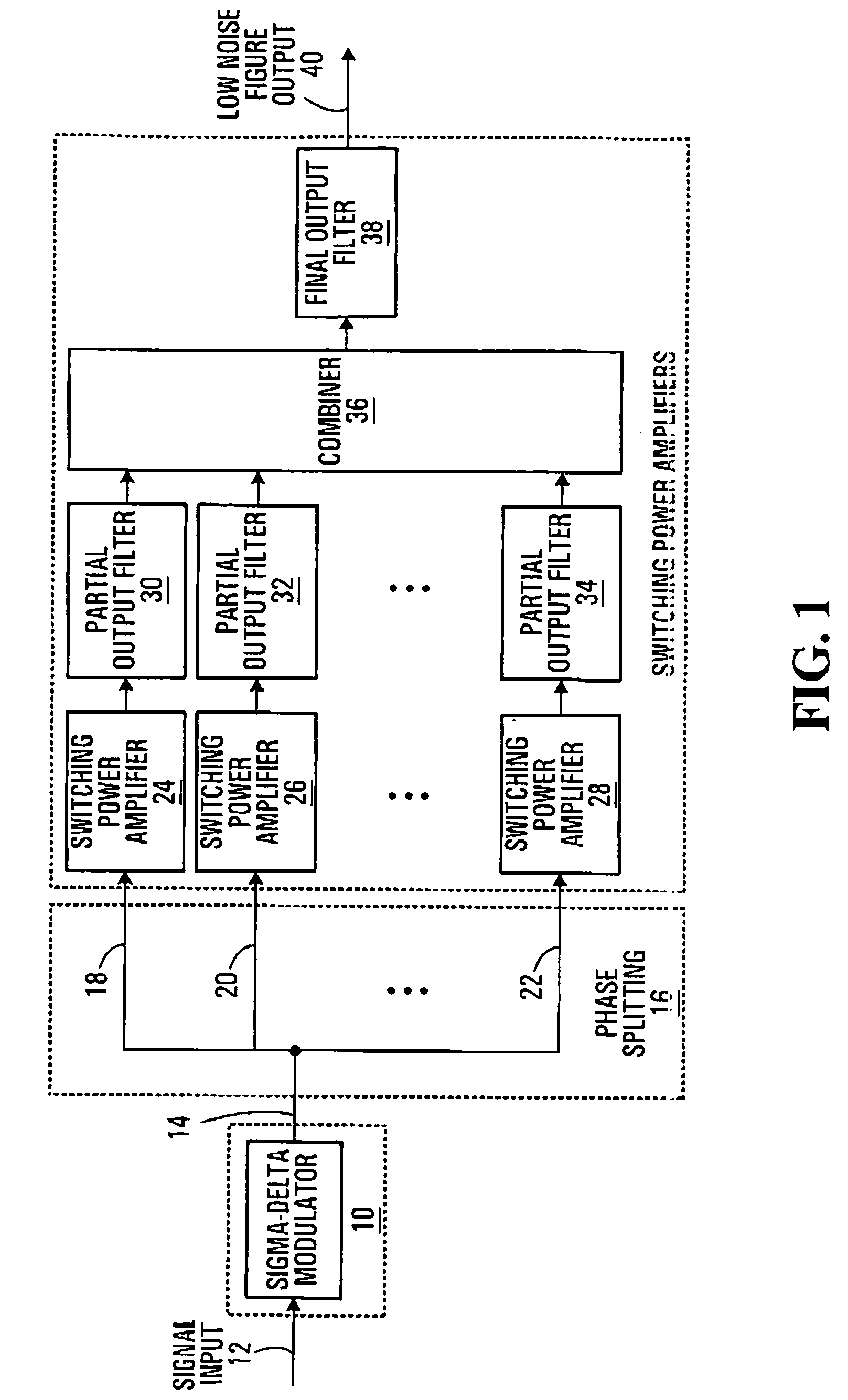
[0036] Referring now to FIG. 1, shown is a block diagram of a high-efficiency amplification system using an N-level Sigma-Delta modulator, N≧3 as provided by an embodiment of the invention. The Sigma-Delta modulator 10 is connected to receive an input signal and produce an N-level Sigma-Delta modulated output signal 14. A phase splitting function generally indicated at 16 takes the Sigma-Delta modulated signal 14 and produces a set of N−1 “phases”18,20,22 (only three shown). The N−1 phases 18,20,22 collectively sum to equal the Sigma-Delta modulated signal 14 at any instant. Each of the N−1 phases 18,20,22 is connected to the input of a respective one of N−1 switching power amplifiers 24,26,28 (only three shown). The outputs of the switching power amplifiers 24,26,28 are connected to respective partial output filters 30,32,34 (only three shown). The outputs of the partial output filters 30,32,34 are connected to inputs of a combiner 36 having an output connected to a final output fi...


PUM


Abstract

Methods and apparatus are provided for efficiently amplifying or converting a signal. An input signal is decomposed into a plurality of two state signals, each two state signal having a respective on level and off level. This may involve sigma-delta modulation and phase splitting. For amplifier applications, each of the two state signals is amplified with a respective switching power amplifier to produce a respective amplified signal. The amplified signals are combined to produce an amplified version of the input signal. Signals may be adjusted for impairments associated with a subsequent processing operation such as the combining.

Description

CROSS-REFERENCE TO RELATED APPLICATION [0001] This application is a continuation-in-part of U.S. patent application Ser. No. 10 / 449,105, filed on Jun. 2, 2003, entitled “HIGH-EFFICIENCY AMPLIFIER AND METHOD”, and incorporated in its entirety herein by reference.FIELD OF THE INVENTION [0002] The invention relates to high-efficiency amplifiers, high-performance and high-frequency digital to analog converters, and methods. BACKGROUND OF THE INVENTION [0003] Power amplifiers account for a significant portion of the capital and operational expense in current wireless base station designs. One method of reducing this expense is to increase the overall efficiency of these amplifiers. In order to obtain high-efficiency amplifiers, one approach which has been tried is to modulate the amplifier's PSU (power supply unit) in order to track the input envelope of the modulated signal. This in turn requires that one must have a high-efficiency PSU which supports the desire to modulate the PSU, whi...

Claims


Application Information

Patent Timeline
Patent Type & Authority Applications(United States)
IPC IPC(8): H03F1/02H03F3/217H03F3/387
CPCH03F1/0205H03F1/0211H03F1/0227H03F1/08H03F2200/504H03F3/217H03F3/2175H03F3/2178H03F2200/331H03F3/211
Inventor MORRIS, BRADLEY JOHNFULLER, ARTHUR THOMAS GERALD
Owner MICROSOFT TECH LICENSING LLC
Why Eureka
Try Eureka