Projector with tilt angle measuring device

a technology of tilt angle and measuring device, which is applied in the field of projectors, can solve the problems of complex structure, inability to obtain the detection speed necessary for realizing distortion correction in real time, and image distortion, and achieve the effect of accurately measuring the tilt angle of the screen

Inactive Publication Date: 2005-03-24
NEC VIEWTECH
View PDF0 Cites 54 Cited by
  • Summary
  • Abstract
  • Description
  • Claims
  • Application Information

AI Technical Summary

Benefits of technology

[0008] It is an object of the present invention to provide a projector having a tilt angle measurement device for correcting image distortion; this projector being able to accurately measure the angle of tilt of a screen in the horizontal and vertical direction with respect to the axis of projection of the projector by means of a simple configuration.

Problems solved by technology

However, in contrast with a display-type television, the image plane of a projector may be a screen or a wall, and the problem therefore arises of distortion in the image that results from the relation between the axis of projection of the projector and the projection surface.
The method disclosed in Japanese Patent Laid-Open Publication No. 169211 / 01 requires control of the angle of the laser pointer and therefore entails a complex structure.
The method that is disclosed in Japanese Patent Laid-Open Publication No. 197249 / 97 requires shifting of the image pattern on the screen to detect the angle, and therefore cannot obtain the detection speed necessary for realizing distortion correction in real time.
The method that is disclosed in Japanese Patent Laid-Open Publication No. 5278 / 03 assumes the perpendicular installation of the screen and therefore cannot provide accurate correction of distortion when the screen is not installed perpendicularly or when the screen is tilted in the horizontal direction with respect to the axis of projection of the projector.

Method used


Image

  • Projector with tilt angle measuring device
  • Projector with tilt angle measuring device
  • Projector with tilt angle measuring device

Examples


Embodiment Construction

[0042] In the interest of facilitating understanding, identical constituent elements are referred to by the same names and reference numerals in all modes and working examples in each of the drawings of the present description.

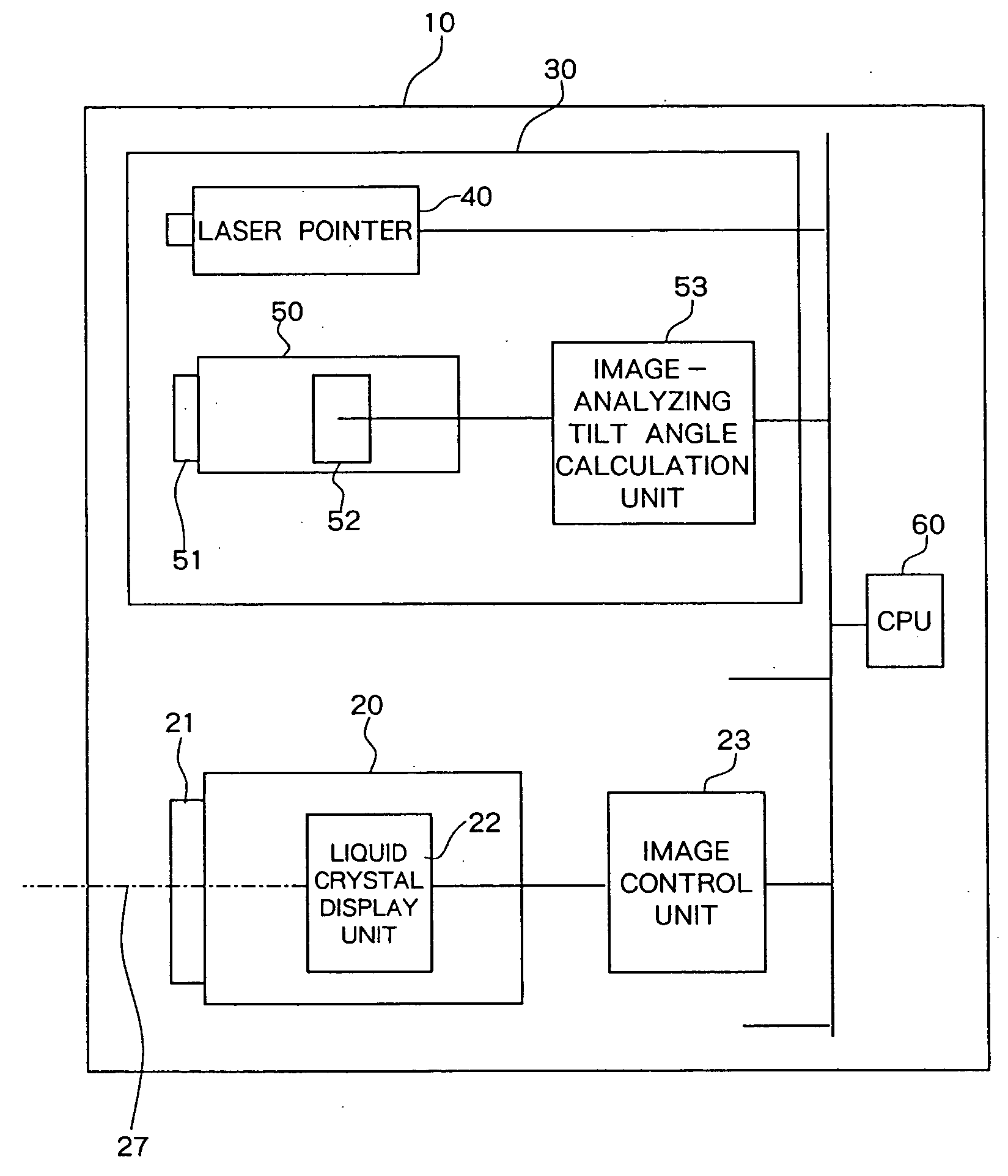
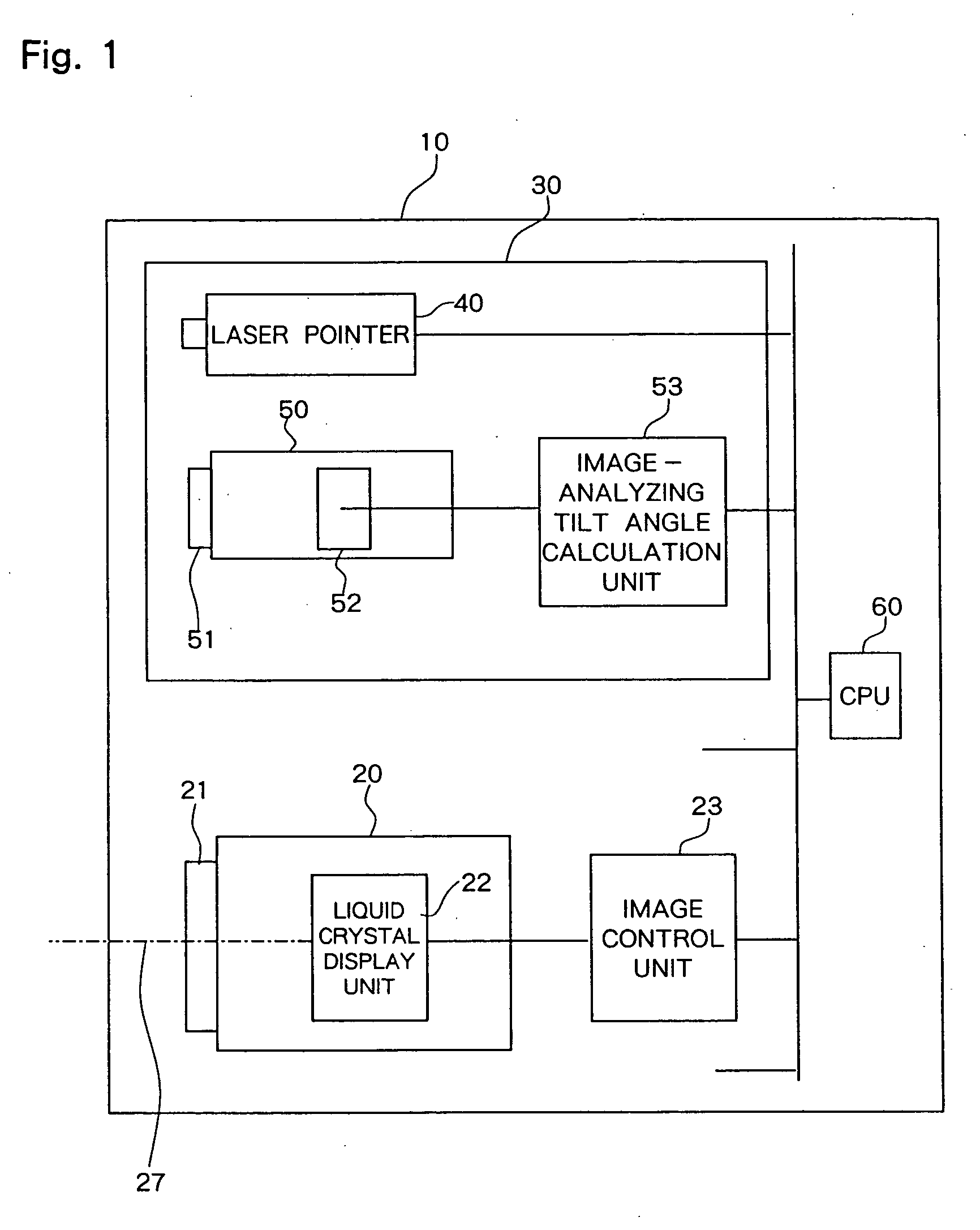
[0043] The present explanation regards a case in which projector 10 is a liquid crystal projector, but the present invention can still be applied to a DLP (registered trademark) (Digital Light Processing) projector. In place of liquid crystal display unit 22 that is used for a liquid crystal projector, a DLP projector is normally provided with a DMD (Digital Micromirror Device) display unit, a color wheel, and a light source.

[0044] As shown in FIG. 1, projector 10 in the first mode of the present invention is provided with: projection device 20 that includes projection lens 21 and liquid crystal display unit 22; image control unit 23 for controlling the image of liquid crystal display unit 22; tilt angle measurement device 30; and CPU (Central Processing Uni...


PUM


Abstract

A projector having a tilt angle measurement device is provided with: a projection device for projecting an image onto a projection surface; a tilt angle measurement device for calculating the tilt angle that is formed between the axis of projection of the projection device and the projection surface; and an image control unit for controlling the output image from the projection device in accordance with the tilt angle that is calculated and thus correcting distortion in the image that is projected onto the projection surface. The tilt angle measurement device includes: a light guide unit that is provided on the projection-side surface of the case of the projector and separated from the axis of projection in a prescribed direction; a photodetection element for photodetecting, by way of the light guide unit, reflected light from at least two points that are projected onto the projection surface; and a tilt angle calculation unit for calculating the tilt angle that is formed between the axis of projection of the projection device and the projection surface based on photodetection position information of the reflected light of the photodetection element.

Description

BACKGROUND OF THE INVENTION [0001] 1. Field of the Invention [0002] The present invention relates to a projector, and more particularly, to a projector having a tilt angle measuring device for calculating the tilt angle of the optical axis of projection of the projection device of the projector and the projection surface. [0003] 2. Description of the Related Art [0004] The rapid progress of liquid crystal technology and DLP (registered trademark) (Digital Light Processing) technology has been accompanied by advances in the development of more compact and more highly functional projectors. With this development, the use of projectors of the prior art having the purpose of image projection has expanded, and projectors are now receiving attention as large-sized display devices for taking the place of display-type televisions for home use. [0005] However, in contrast with a display-type television, the image plane of a projector may be a screen or a wall, and the problem therefore arise...

Claims


Application Information

Patent Timeline
Patent Type & Authority Applications(United States)
IPC IPC(8): G03B21/00G03B21/14G03B21/26H04N5/74H04N17/00
CPCG03B21/14H04N9/3194H04N9/3185H04N5/7416G03B21/145
Inventor TAMURA, YOUICHI
Owner NEC VIEWTECH
Why Eureka
Try Eureka