Optical rotating data transmission device having an unobstructed inner diameter

a transmission device and optical technology, applied in the field of optical sensors, can solve the problems of inability to use devices, inability to transmit broadband data with modulation signals, and relatively high fabrication costs, and achieve the effect of simple and cost-effective, easy to distinguish, and simpl

Inactive Publication Date: 2005-03-24
SCHLEIFRING & APPBAU
View PDF9 Cites 21 Cited by
  • Summary
  • Abstract
  • Description
  • Claims
  • Application Information

AI Technical Summary

Benefits of technology

[0072] In another advantageous embodiment of the invention, at least one exit face is provided with an active optical coating. This optical coating comprises a material for a wavelength conversion of the transmitted light. It is preferably based on at least one non-linear optical effect. Preferably this is a fluorescence effect. By means of the wavelength conversion, stray light from the light source can be distinguished easily from a wanted signal now having a converted wavelength. Likewise, in this way and manner different channels, for example with wavelength conversion or without wavelength conversion, can be separated from each other. Furthermore, a known time constant of a non-linear optical effect, for example a fluorescence effect, can be utilized for time measurement, and therewith for distance measurement by an evaluation of transit times.
[0073] For a separation of two directions, it is of particular advantage to use two different fluorescent materials excited by a common light source and radiating at different wavelengths.
[0074] The above-described optical sensors are of particular advantage when used together with devices for optical transmission in accordance with the present invention.
[0075] A very critical issue is the design of the first light couplers 4. In most applications it is necessary to couple light into two opposite directions of the light guide 3. This could be done for example by using fiber-splitters which split light from a single light source 73 into two approximately equal light paths 74 and 75. In some cases, especially when very high data rates or several channels have to be transmitted, the transmission system would be polarization-dependent. Fiber couplers which maintain the polarization of the coupled optical signal are very expensive. Therefore one aspect of the invention is to provide a simple and cost effective coupler which preferably does not change the polarization of the light being coupled.

Problems solved by technology

A basic problem here is that of designing a means for passing light along the periphery of the device, and suitable means for coupling in and coupling out light.
However, this device has a series of disadvantages.
Furthermore, fabrication costs are relatively high, because of the oppositely located mirror surfaces.
Broadband data transmission with modulation signal period lengths substantially shorter than the transit time of the signal around the circumference of the device is not possible, because at positions of the receiver close to the transmitter, a multiple-path reception of signals occurs.
However, this patent specification also describes no effective solution of the problem of bandwidth limitation.
Furthermore, the suggested coupling in or coupling out of light by means of blunt fiber ends can be put into practice only with extremely poor efficiency.
However, here too a high attenuation along the optical transmission path results, because the coupling-in mirrors cannot be positioned as closely as desired to the mirror-coated cylinder.
Furthermore, an unavoidable fanning-out of the light beam on the plane mirror surface results in an additional deterioration of the efficiency.
Moreover, the mechanical construction of the coupling-out element involves special outlay, and is therefore subject to failure, and costly.
Finally, the problem of band-width limitation also is not solved.
Here too, the limitation applies that the duration of the period of the modulation signal must be substantially smaller than the transit time of the light around the circumference of the device.
However, this system involves very high outlay, is expensive to manufacture, and is only suitable for small diameters.
Furthermore, here too the bandwidth problem is unsolved.
Thus, the costs of the system increase in proportion to the bandwidth.
This arrangement has the decisive disadvantage that the coupling medium must be directly in contact with the fiber core.
However, this kind of system is hardly usable for arrangements in which the transmitter and the receiver move relative to each other, because here the coupling medium must slide with high velocity along a fiber core which is usually very thin and sensitive.
However, with conventional highly precise bearings, this accuracy can be achieved only with small dimensions of the entire arrangement.
Thus, at present this system cannot be employed, for example, in computer tomographs having a diameter of 1.5 meters and circumferential speeds of up to 20 m / s.

Method used


Image

  • Optical rotating data transmission device having an unobstructed inner diameter
  • Optical rotating data transmission device having an unobstructed inner diameter
  • Optical rotating data transmission device having an unobstructed inner diameter

Examples


Embodiment Construction

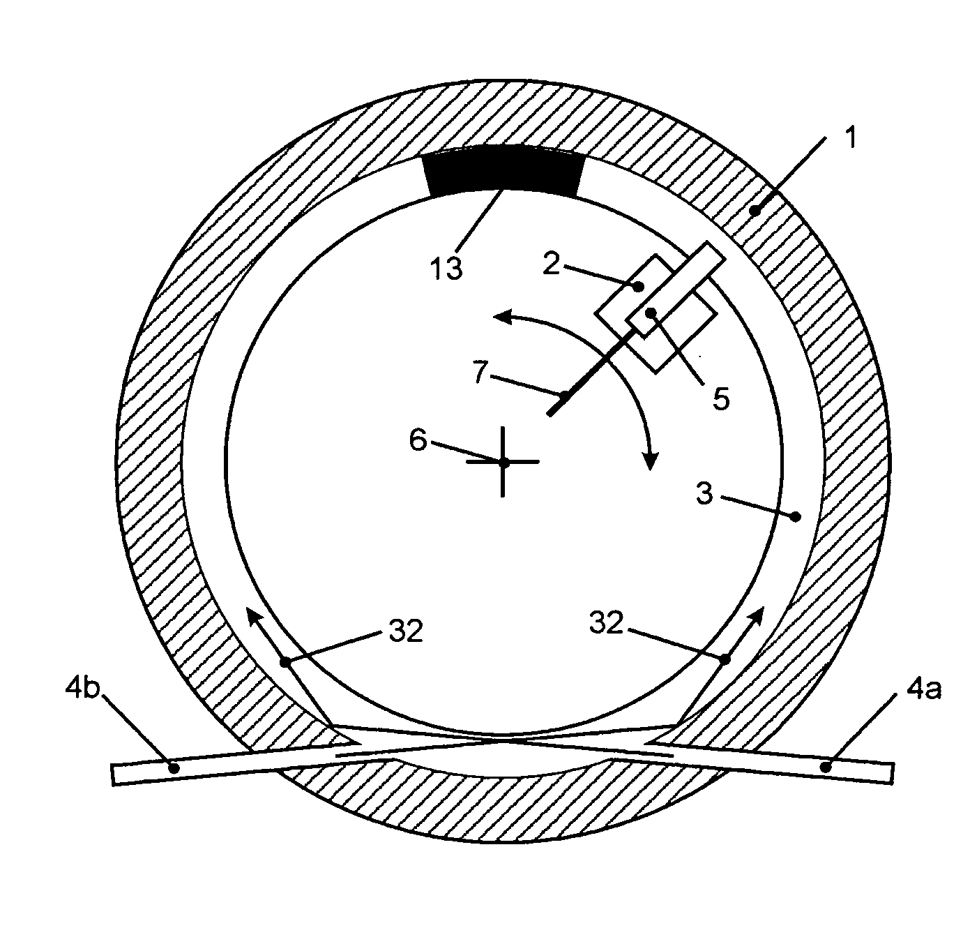
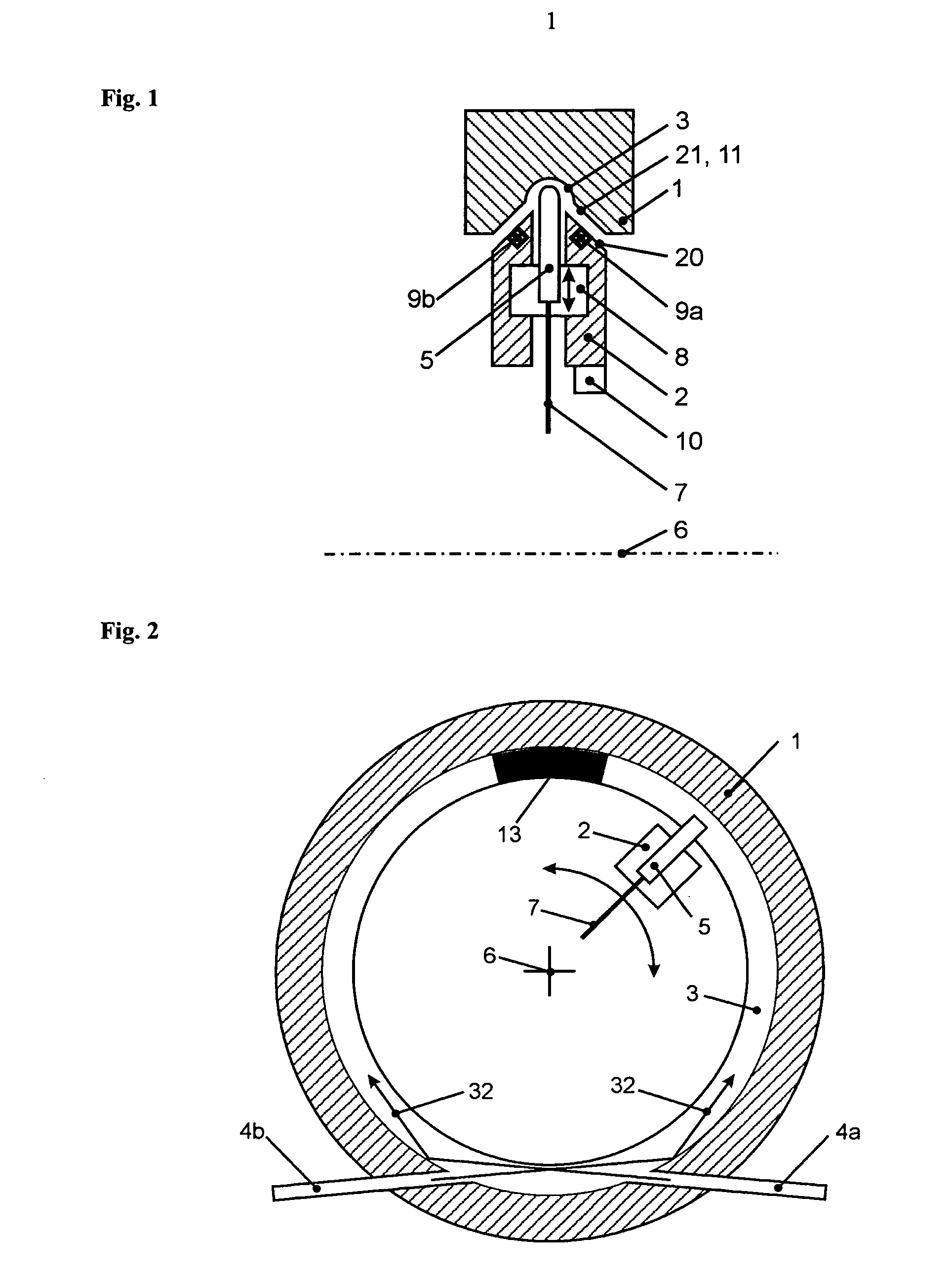
[0012] The invention is based on the object of designing a device of relatively low cost for transmitting optical signals between two units which are rotatable relative to each other, so that a reliable transmission with low optical attenuation is made possible for large diameters, high mechanical movement speeds, and high data rates. Furthermore, it is the object of a special development of the invention to design the device so that even signals having period lengths which are small in comparison with the time of the propagation of the light around the circumference of the device may be transmitted.

[0013] A further object of the invention is that of further developing a fiber-optical sensor as known in the art so that it is adapted to perform measurements laterally of the fiber. Furthermore, this fiber-optical sensor is required to be of small constructional size and inexpensive, and therefore capable of being built without any additional separate optical components for beam defle...


PUM


Abstract

In a device of the invention for transmitting modulated optical signals between a first unit and a second unit, the first unit is supported to be rotatable relative to the second unit. The device comprises a light guide along a circular track on the first unit, a first light coupler for coupling light into or out of the light guide, and a second light coupler for coupling light into or out of the light guide and disposed on the second unit and movable relative to the means for guiding light. For an achievement of a high quality of transmission, a regulating means for the position of the coupling elements relative to the light guide, or a hydrodynamic bearing means is provided. An optical light-guiding fiber of the invention for conveying optical signals from an optical transmitter to an optical receiver has a light exit face and means for deflecting light emerging from the fiber in a direction that deviates from a longitudinal axis of the fiber.

Description

[0001] This application is a continuation of International Application No. PCT / DE03 / 00438 filed on Feb. 13, 2003, which designates the United States and claims priority to German Application Nos. 10246141.4 filed Oct. 1, 2002; 10206589.6 filed Feb. 15, 2002; 10206591.8 filed Feb. 15, 2002; and 10256634.8 filed Dec. 3, 2002. In addition, this application claims priority to German Application Nos. 102004026945.9 filed Jun. 1, 2004 and 102004037684.0 filed Aug. 2, 2004.TECHNICAL FIELD [0002] The invention relates to a device for transmitting optical signals between units that are rotatable relative to each other. Devices of this kind are preferably employed in computer tomographs. Furthermore the invention relates to an optical sensor. PRIOR ART [0003] For transmitting optical signals between units that are rotatable relative to each other, various devices, having in particular an unobstructed inner diameter, are known. A basic problem here is that of designing a means for passing ligh...

Claims


Application Information

Patent Timeline
Patent Type & Authority Applications(United States)
IPC IPC(8): G02B5/18G02B6/35G02B6/36
CPCG02B6/3604G02B5/1857
Inventor POISEL, HANSSTARK, MARKUSSCHILLING, HARRYRANK, MATTHIASSCHOPPEL, GUNTHER
Owner SCHLEIFRING & APPBAU
Why Eureka
Try Eureka