

Sonication to selectively lyse different cell types
a cell type and cell type technology, applied in the field of selective lysing different cell types, can solve the problems of shock waves radiating through the sample, protocol that is difficult to repeat, and physical lysis often requires expensive equipmen
- Summary
- Abstract
- Description
- Claims
- Application Information
AI Technical Summary
Benefits of technology
Problems solved by technology
Method used
Image

Examples
Embodiment Construction
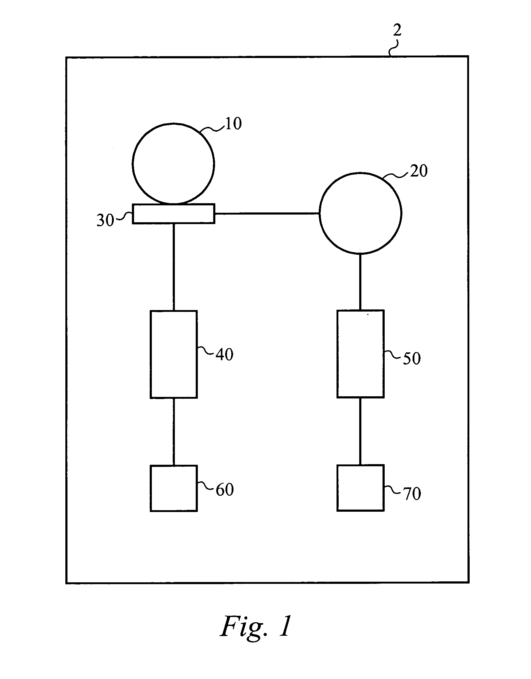
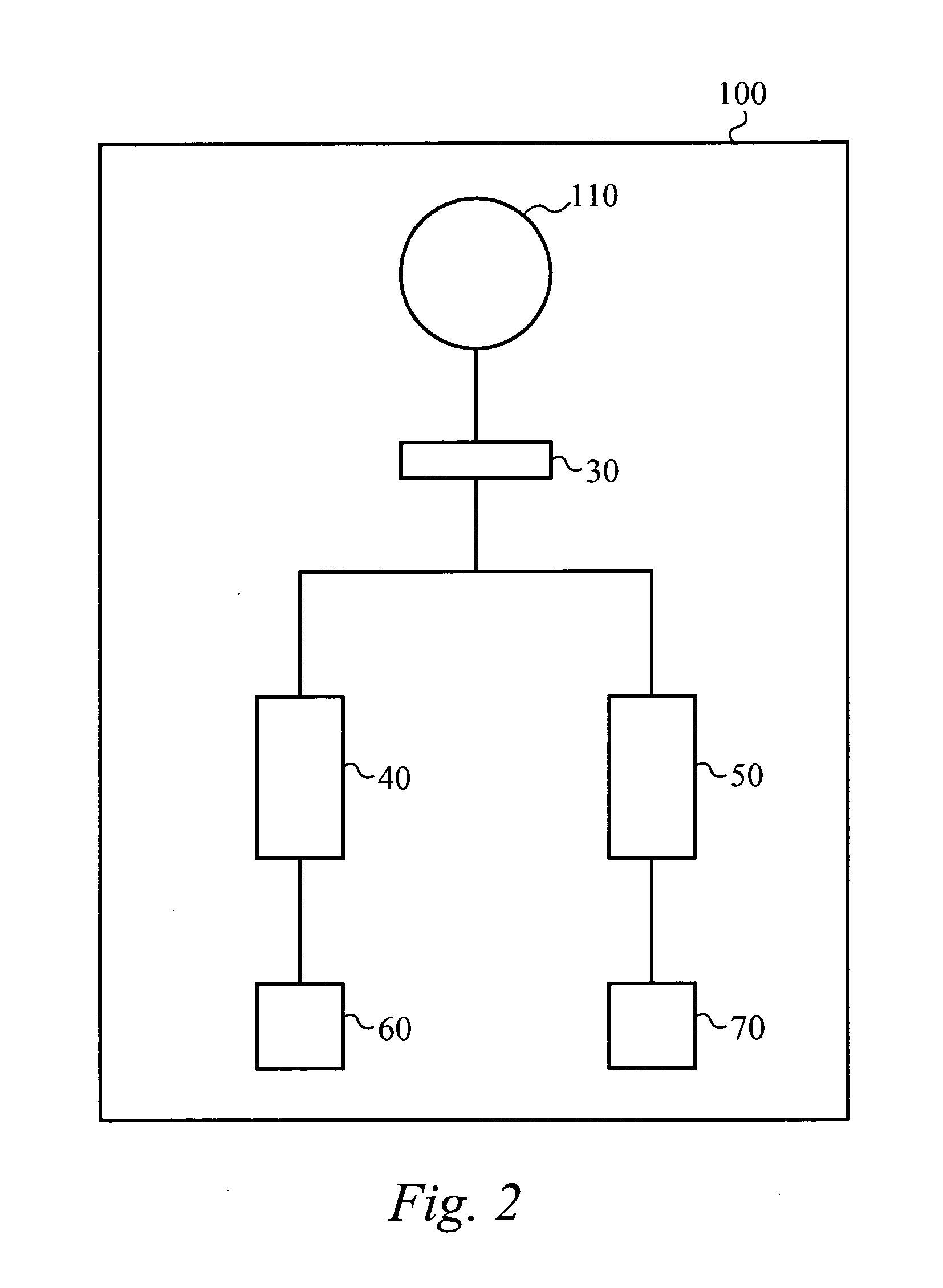
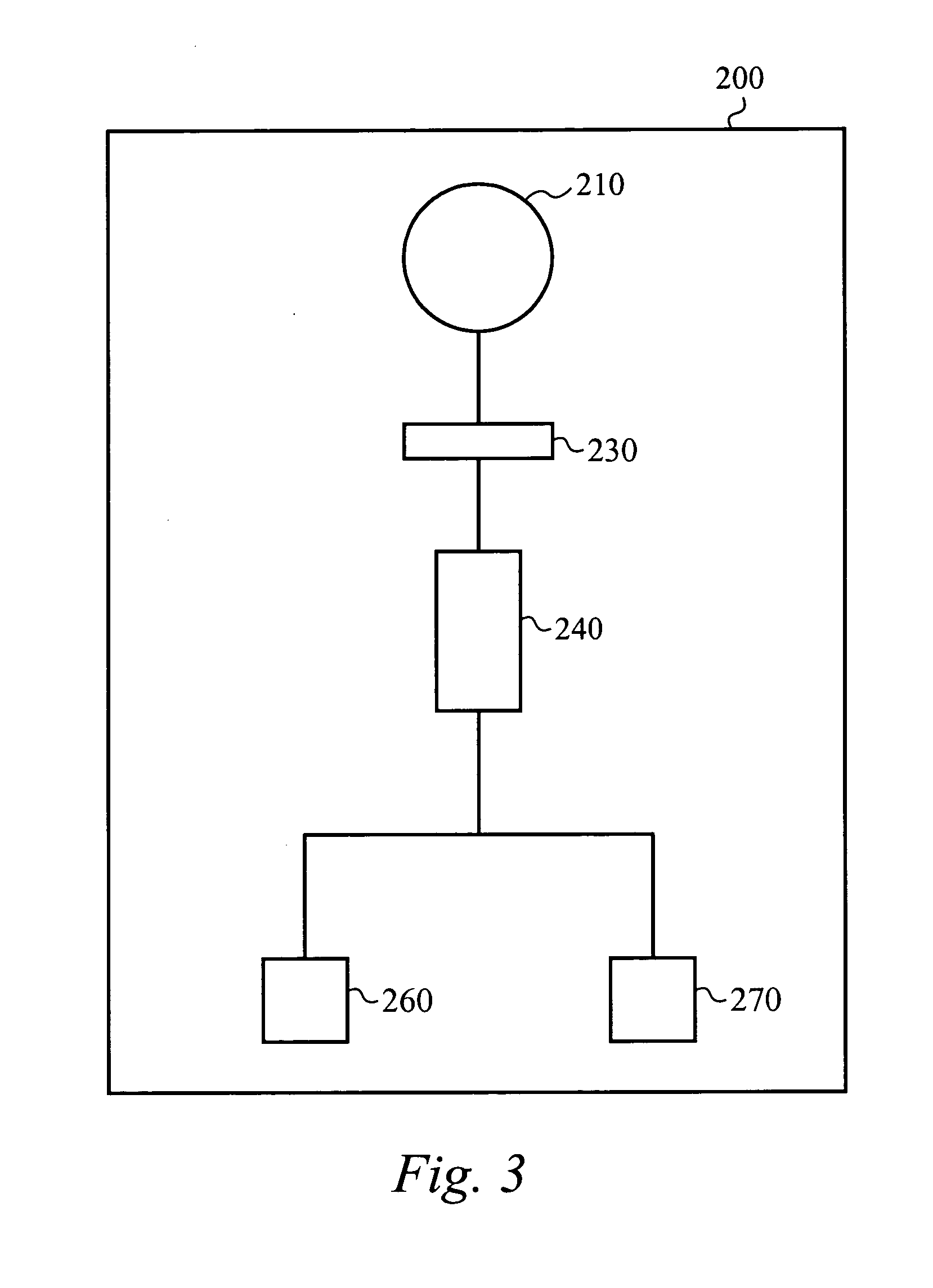
[0018] Embodiments of a sonication apparatus of the present invention are directed to a microfluidic-based system to automate differential extraction of specific cell types within a mixed sample. The microfluidic-based system includes a sonication module for selective cell lysis, separating means to eliminate centrifugation, high surface area pillar chip modules to purify DNA from a cell lysate, and microfluidic circuitry to integrate the steps in an automated platform.
[0019] The sonication module can include one or more sonication chambers. In the preferred embodiment, the sonication module includes two sonication chambers. Alternatively, one sonication chamber can be used. Still alternatively, three or more sonication chambers can be used when a mixed sample includes three or more different cell types. Each of these sonication module configurations is discussed in greater detail below.
[0020] Conventional sonication is an established physical method for rapid and non-specific lys...
PUM
 Abstract
Description
Claims
Application Information