Microfluidic differential extraction cartridge

a technology microfluidics, which is applied in the field of differential cell lysis methods and apparatuses, can solve the problems of shock waves radiating through the sample, physical lysis often requires expensive, cumbersome equipment,

Inactive Publication Date: 2005-03-24
MICROFLUIDIC SYST
View PDF22 Cites 41 Cited by
  • Summary
  • Abstract
  • Description
  • Claims
  • Application Information

AI Technical Summary

Problems solved by technology

Physical lysis often requires expensive, cumbersome equipment and involves protocols that are difficult to repeat due to variability in the apparatus.
Mechanical energy from the probe initiates the formation of microscopic vapor bubbles that form momentarily and implode, causing shock waves to radiate through the sample.
The sonic energy delivered to a sample using this method is variable, and not repeatable for a necessary level of precision.
Sample types and matrices can vary considerably, and the entire sample preparation process can be very time consuming and labor intensive.
Rape kits, containing swab samples of biological evidence collected in hospitals from victims of sexual assault, are amongst the most common, yet difficult, sample types to process since the swabs potentially contain a mixture of female epithelial cells and male sperm cells.
This conventional process takes hours, sometimes days.

Method used


Image

  • Microfluidic differential extraction cartridge
  • Microfluidic differential extraction cartridge
  • Microfluidic differential extraction cartridge

Examples


first embodiment

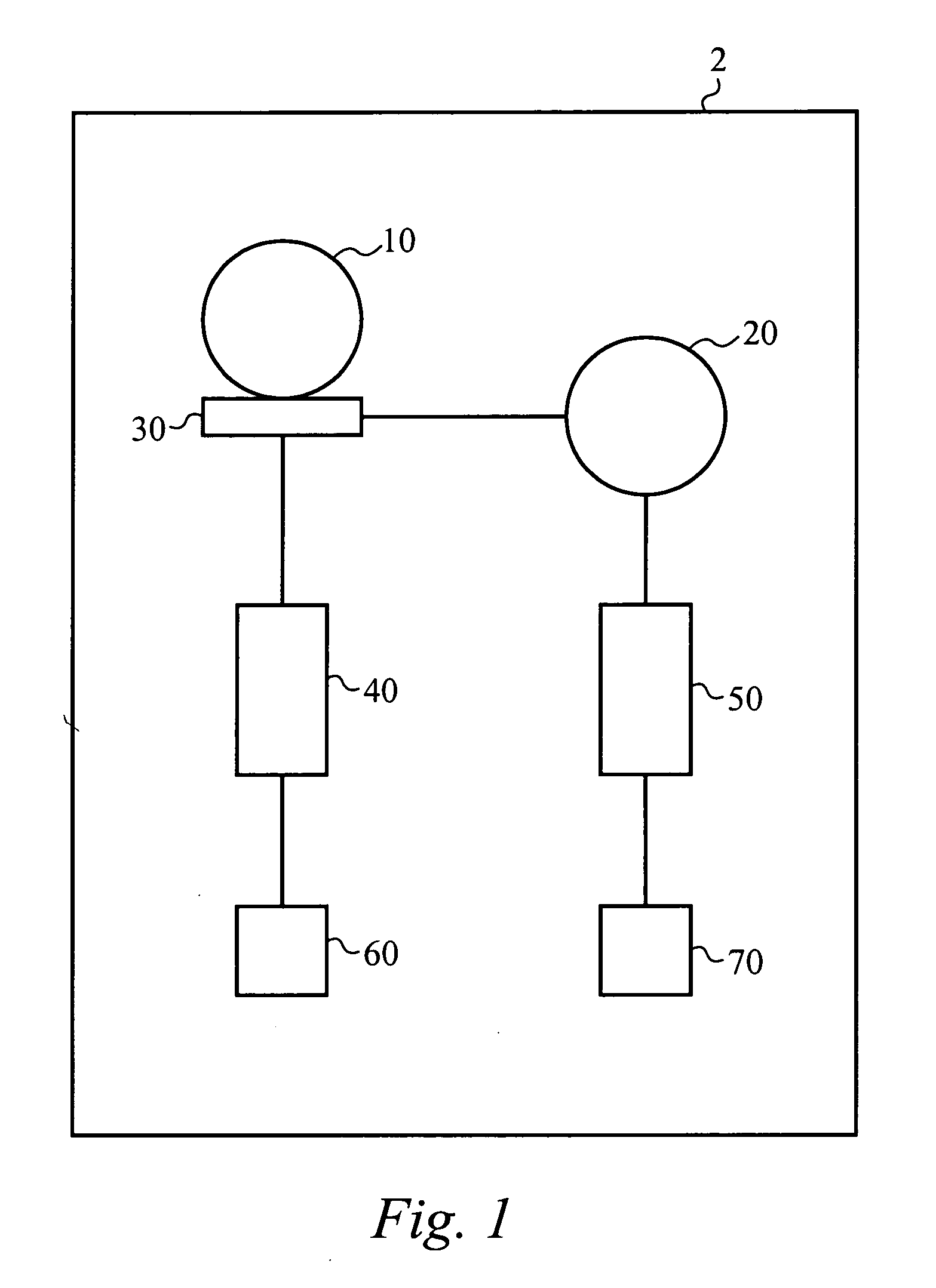
[0030]FIG. 1 illustrates a conceptual block diagram of a sonication apparatus 2 to selectively lyse a mixed sample using sonication according to the present invention. The mixed sample includes at least two different cell types. For example, the sample can be a rape kit sample that includes female epithelial cells and male sperm cells. A first cell type within the mixed sample is lysed at a first sonication energy, and a second cell type is lysed at a second sonication energy. The apparatus 2 includes a first sonication chamber 10, a second sonication chamber 20, a separating means 30, a first purification chip 40, a second purification chip 50, a first output vessel 60, and a second output vessel 70, each of which is coupled using microfluidic circuitry, which is discussed in greater detail below. The mixed sample is placed in the first sonication chamber 10. The first sonication chamber 10 provides the first sonication energy to the mixed sample, thereby lysing the first cell type...

second embodiment

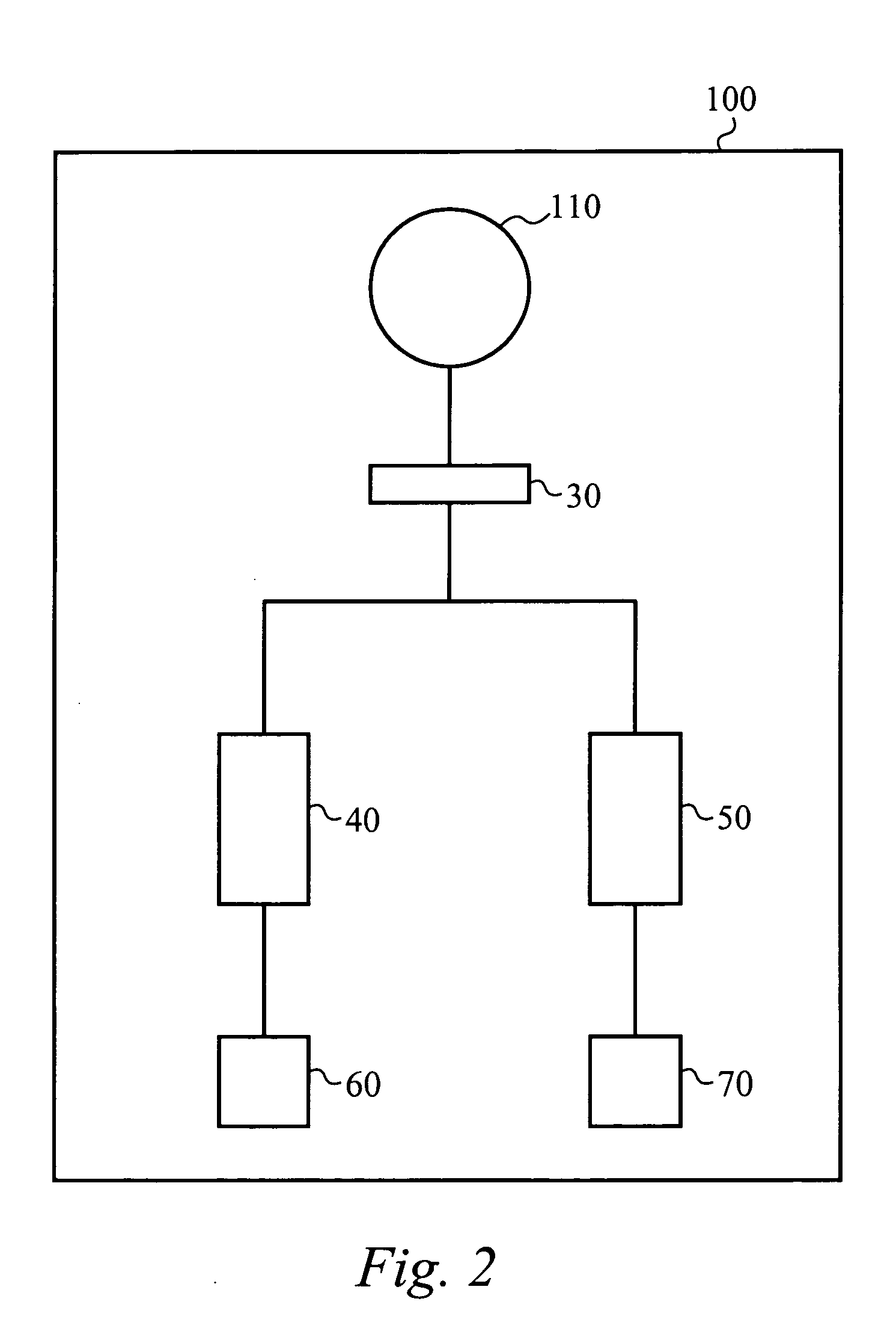
[0038]FIG. 2 illustrates a conceptual block diagram of a sonication apparatus 100 to selectively lyse a mixed sample using sonication according to the present invention. The sonication apparatus 100 operates similarly to the sonication apparatus 2 except that the two sonication chambers 10 and 20 are replaced by a single sonication chamber 110. In operation, the first sonication chamber 110 receives the mixed sample and the first sonication energy is applied, thereby lysing the first cell type and producing the first lysate. The first lysate is separated from the mixed sample by the separating means 30, such that the first lysate passes through the separating means 30 and the intact second cell type is blocked by the separating means 30. The first lysate is directed to the first purification chip 40 as described above in relation to the preferred sonication apparatus 2. The blocked second cell type is back flushed from the separating means 30 to the sonication chamber 110. The sonic...

third embodiment

[0039]FIG. 3 illustrates a conceptual block diagram of a sonication apparatus 200 to selectively lyse a mixed sample using sonication according to the present invention. The sonication apparatus 200 includes a single sonication chamber 210 and a single purification chip 240. The sonication chamber 210 receives the mixed sample and provides the first sonication energy as described in detail above. The first lysate passes through the separating means 230 to the purification chip 240. The purification chip 240 purifies and concentrates the first DNA from within the first lysate and the remaining portion of the first lysate passes though as waste. Te collected first DNA is flushed from the purification chip 240 and is collected in the first output vessel 260. Flushing the first DNA also acts to clean the purification chip 240. Alternatively, after the first DNA is flushed from the purification chip 240 to the first output vessel 260, a cleaning step is performed in which the purificatio...


PUM

PropertyMeasurementUnit
diameteraaaaaaaaaa
diameteraaaaaaaaaa
energyaaaaaaaaaa

Abstract

A differential extraction system is directed to a microfluidic-based integrated cartridge to automate differential extraction of specific cell types within a mixed sample. The integrated cartridge includes a sonication module for selective cell lysis, separating means to eliminate centrifugation, high surface area pillar chip modules to purify DNA from a cell lysate, and microfluidic circuitry to integrate the steps in an automated platform.

Description

RELATED APPLICATIONS [0001] This application is a continuation-in-part of U.S. patent application Ser. No., ______, filed Sep. 17, 2004, and entitled “Sonication to Selectively Lyse Different Cell Types”, which claims priority under 35 U.S.C. 119(e) of the co-pending U.S. Provisional Patent Application Ser. No. 60 / 504,072, filed Sep. 19, 2003, and entitled “Microfluidic Differential Extraction Instrument”, both of which are hereby incorporated by reference.FIELD OF THE INVENTION [0002] The invention relates to a method and apparatus for differential cell lysis. In particular, the invention relates to differential cell lysis using an integrated cartridge. BACKGROUND OF THE INVENTION [0003] Cell lysis is the destruction, or disruption, of a cell's membrane or wall, which breaks open the cell and exposes its contents. Many techniques are available for the disruption of cells, including physical and detergent-based methods. Physical lysis often requires expensive, cumbersome equipment a...

Claims


Application Information

Patent Timeline
Patent Type & Authority Applications(United States)
IPC IPC(8): B01L3/00C12M1/42C12NC12N1/06C12N13/00C12Q1/04
CPCB01L3/5025C12N13/00B01L2200/0631B01L2200/0647B01L2200/10B01L2300/0636B01L2300/0864B01L2300/0867B01L2300/087B01L2300/1827B01L2400/0409B01L2400/0487C12M47/06C12N1/06C12N1/066B01L3/5027
Inventor YUAN, BOBAFLATOONI, NINA
Owner MICROFLUIDIC SYST
Why Eureka
Try Eureka