Sensors and associated methods for controlling a vacuum cleaner

a technology of vacuum cleaners and sensors, applied in the direction of process and machine control, distance measurement, instruments, etc., can solve the problems of brush motor current, no current robotic canister-like vacuum cleaner senses suction airflow, and no technology of light wave sensors

Active Publication Date: 2005-03-24
ROYAL APPLIANCE MFG
View PDF30 Cites 127 Cited by
  • Summary
  • Abstract
  • Description
  • Claims
  • Application Information

AI Technical Summary

Benefits of technology

[0024] In still another embodiment, the method includes: a) emitting sonic energy toward a floor being traversed by the vacuum cleaner, b) detecting sonic energy reflected by the floor, c) comparing the detected sonic energy to a predetermined threshold, d) when the detected sonic energy exceeds the predetermined threshold, initiating a first predetermined control procedure, e) when the detected sonic energy does not exceed the predetermined threshold, initiating a second predetermined control procedure, and f) repeating steps a)-e).
[0025] In still yet another embodiment, the method includes: a) emitting sonic energy toward a floor being traversed by the vacuum cleaner, b) detecting the sonic energy reflected by the floor, c) comparing the detected sonic energy to at least one of a plurality of values in a lookup table (LUT),...

Problems solved by technology

Currently, technology and innovation are both limiting factors in the capability of household cleaning robots.
However, none of the current robotic ...

Method used


Image

  • Sensors and associated methods for controlling a vacuum cleaner
  • Sensors and associated methods for controlling a vacuum cleaner
  • Sensors and associated methods for controlling a vacuum cleaner

Examples


Embodiment Construction

[0044] While the invention is described in conjunction with the accompanying drawings, the drawings are for purposes of illustrating exemplary embodiments of the invention and are not to be construed as limiting the invention to such embodiments. It is understood that the invention may take form in various components and arrangement of components and in various steps and arrangement of steps beyond those provided in the drawings and associated description. Within the drawings, like reference numerals denote like elements. It is to be appreciated that the invention is amenable to various applications. For example, a traditional upright vacuum cleaner, a traditional canister vacuum cleaner, a carpet extractor, other types of vacuum cleaners, and other types of robotic vacuums. More generally, this invention is amenable to various types of robotic household appliances, both indoor, such as floor polishers, and outdoor, such as lawnmowers or window washing robots.

[0045] With reference ...


PUM


Abstract

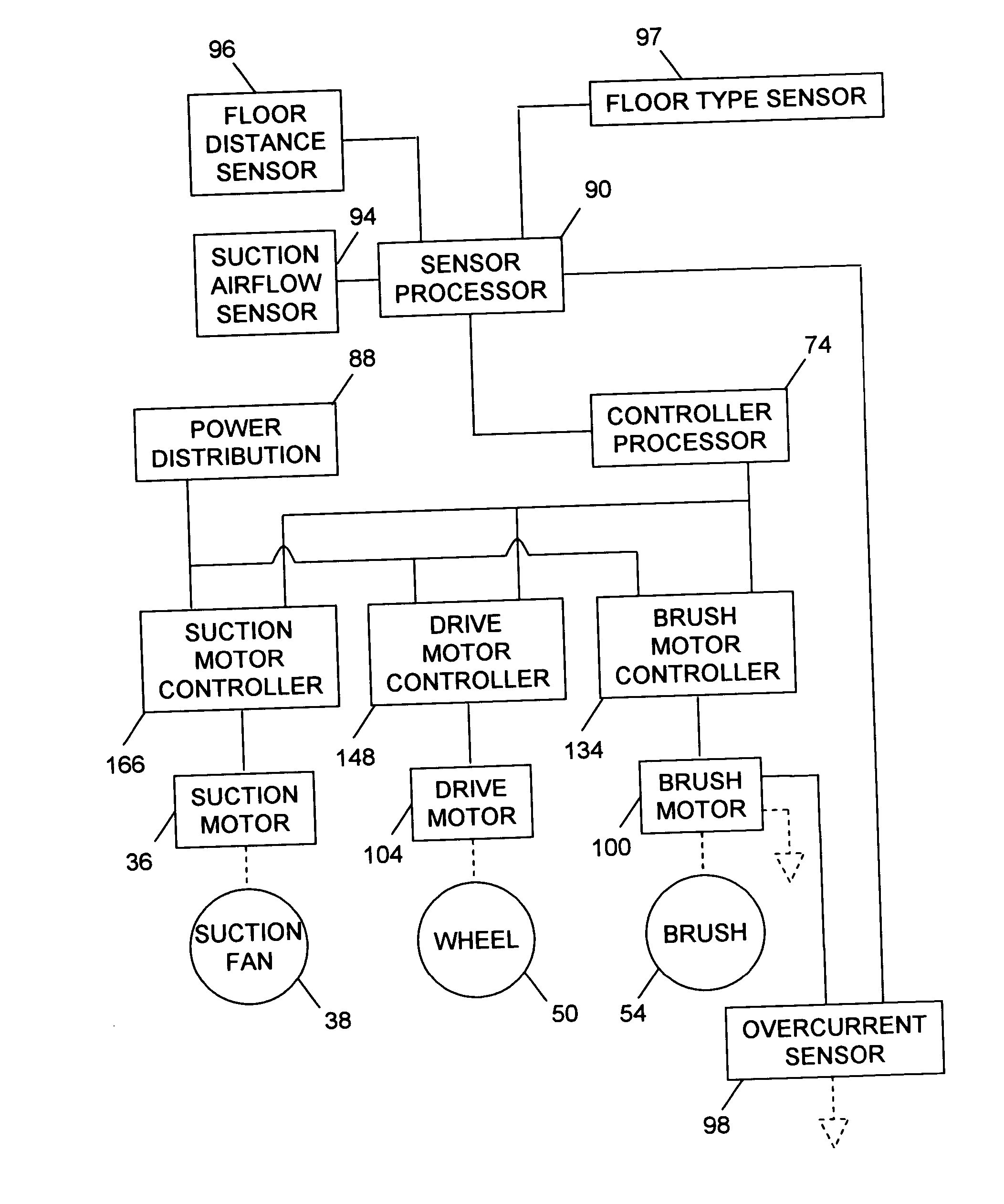
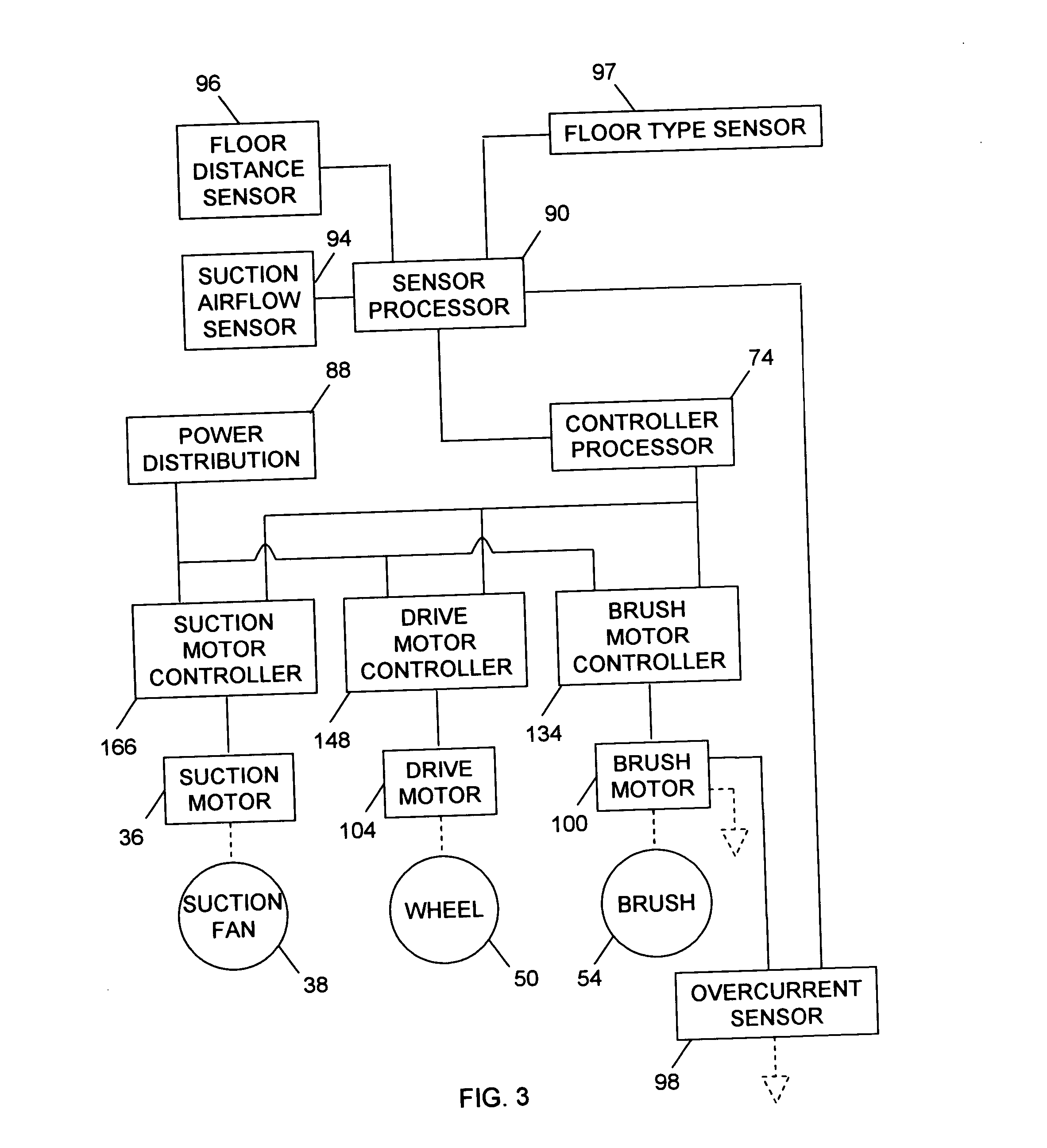
Several methods of controlling a vacuum cleaner (10) using various types of sensors (94, 96, 97, 98) are provided. One method is based on a differential pressure between a suction airflow path and ambient air and includes: detecting the differential pressure, comparing the detected differential pressure to a predetermined threshold, and, when the detected differential pressure is less than the predetermined threshold, initiating a predetermined control procedure. A status indicator (164) is updated based on the detected differential pressure. Another method is based on a level of electrical current flowing through a brush motor (100). Still another method is based on a type or condition of the floor being traversed. Yet another method is based on a distance to a surface of a floor over which the vacuum cleaner is advancing. In another aspect of the invention, a vacuum cleaner is provided. In various combinations, the vacuum cleaner includes a vacuum source (36, 38), a brush motor (100), a drive motor (104), a controller processor (74), a sensor processor (90), an overcurrent sensor (98), a suction airflow sensor (94), a floor type sensor (97), and a floor distance sensor (96).

Description

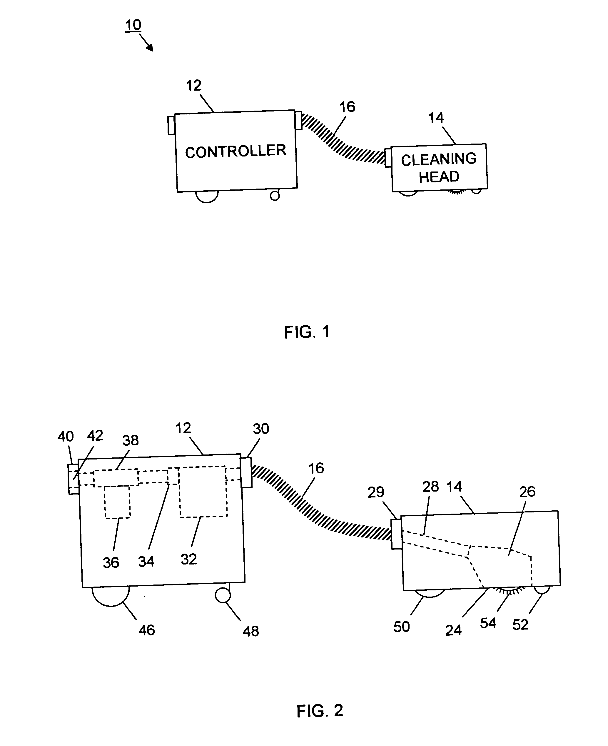
BACKGROUND OF INVENTION [0001] The invention relates to methods of controlling a vacuum cleaner using various types of sensors. It finds particular application in conjunction with a robotic vacuum having a controller, a cleaning head, and an interconnecting hose assembly and will be described with particular reference thereto. However, it is to be appreciated that the invention is also amenable to other applications. For example, a traditional upright vacuum cleaner, a traditional canister vacuum cleaner, a carpet extractor, other types of vacuum cleaners, and other types of robotic vacuums. More generally, this invention is amenable to various types of robotic household appliances, both indoor, such as floor polishers, and outdoor, such as lawnmowers or window washing robots. [0002] It is well known that robots and robot technology can automate routine household tasks eliminating the need for humans to perform these repetitive and time-consuming tasks. Currently, technology and inn...

Claims


Application Information

Patent Timeline
IPC IPC(8): A47L5/00A47L9/00A47L9/28G06F7/00
CPCA47L9/2821A47L9/2842A47L9/2889A47L9/2852A47L9/2857A47L9/2847
Inventor REINDLE, MARK E.KNOX, BRUCE R.SIEGEL, NORMAN
Owner ROYAL APPLIANCE MFG
Why Eureka
Try Eureka