Cleaning tool assembly with a disposable cleaning implement

a cleaning tool and cleaning implement technology, applied in the field of cleaning tools, can solve the problems of significant lateral force being applied to the cleaning implement, and achieve the effect of reducing frictional conta

Active Publication Date: 2005-03-31
THE CLOROX CO
View PDF10 Cites 51 Cited by
  • Summary
  • Abstract
  • Description
  • Claims
  • Application Information

AI Technical Summary

Benefits of technology

[0008] In one aspect of the present invention, the cleaning assembly incorporates an anti-cam device that significantly limits the pivotal motion of the cleaning head fitment in the gripping mechanism, and hence, substantially prevent side ejection from the gripping mechanism. Accordingly, during operational use of the cleaning tool, significantly greater lateral forces can be applied to the cleaning implement during cleaning with a gripping mechanism that would not otherwise be capable of handling such forces. The design of the gripping mechanism, hence, can primarily concentrate on axial retention of the retaining barb.
[0025] Throughout the interior of the maneuvering wand is a plurality of support bearings spaced-apart along the wand cavity. These bearings cooperate with the pushrod to enable unobstructed axial movement thereof between the disengaged condition and the engaged condition. Each support bearing is plate-like, and includes a bearing surface defining a respective aperture enabling reciprocal passage of the pushrod therethrough. Further, each bearing surface of the support bearing is convex shaped to reduce frictional contact with the pushrod during movement between the disengaged condition and the engaged condition.

Problems solved by technology

Accordingly, during operational use of the cleaning tool, significantly greater lateral forces can be applied to the cleaning implement during cleaning with a gripping mechanism that would not otherwise be capable of handling such forces.

Method used


Image

  • Cleaning tool assembly with a disposable cleaning implement
  • Cleaning tool assembly with a disposable cleaning implement
  • Cleaning tool assembly with a disposable cleaning implement

Examples


Embodiment Construction

[0043] While the present invention will be described with reference to a few specific embodiments, the description is illustrative of the invention and is not to be construed as limiting the invention. Various modifications to the present invention can be made to the preferred embodiments by those skilled in the art without departing from the true spirit and scope of the invention as defined by the appended claims. It will be noted here that for a better understanding, like components are designated by like reference numerals throughout the various figures.

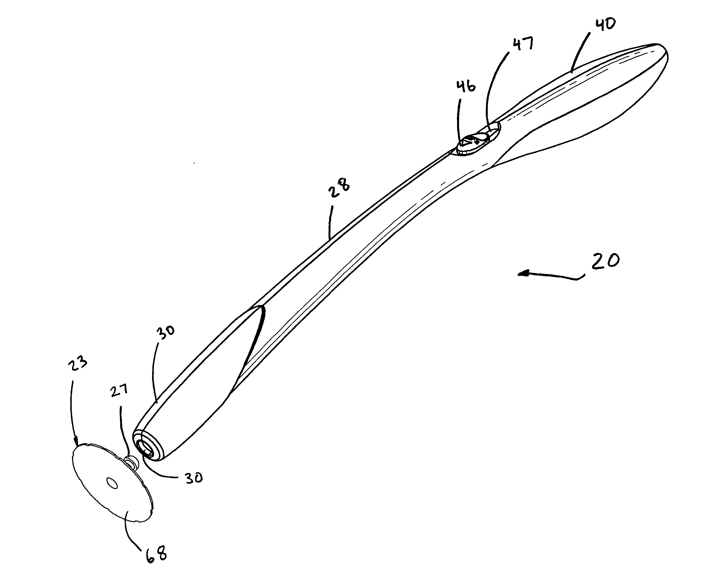
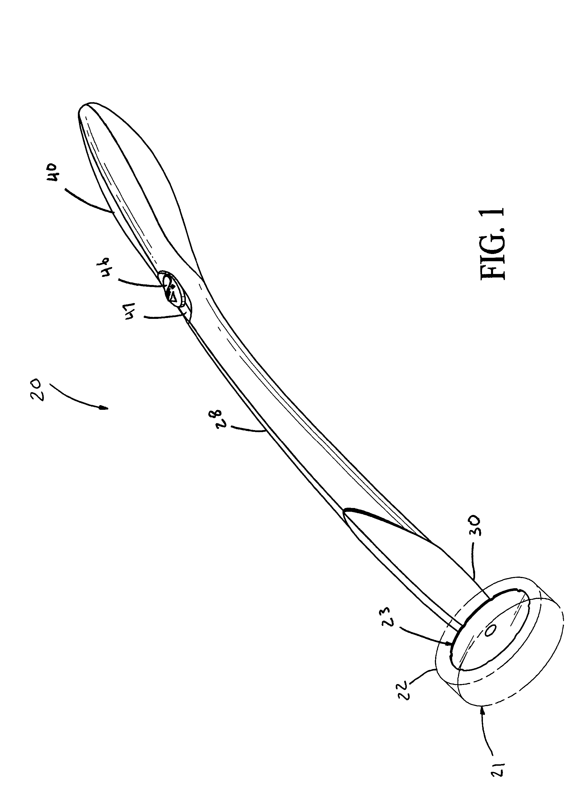
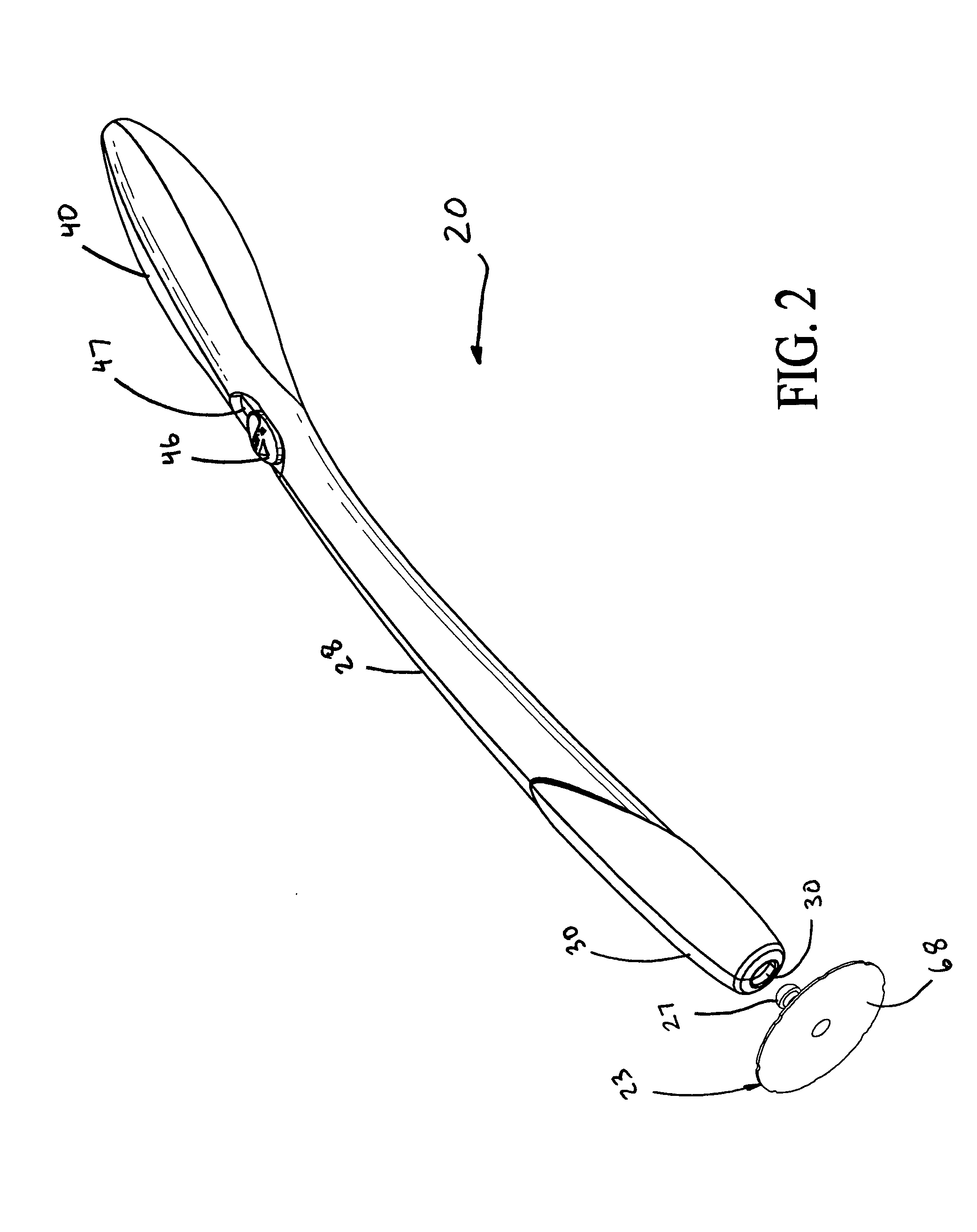
[0044] Referring now to FIGS. 1-5, a cleaning tool assembly, generally designated 20, is provided having a disposable cleaning implement 21 having a cleaning element 22 mounted to a fitment 23. As shown in FIG. 6, the fitment 23 includes an elongated post 26 extending axially from the cleaning element 22 along the longitudinal axis 25 thereof. A retaining barb 27 is positioned at a distal end of the elongated post 26. The tool as...


PUM

PropertyMeasurementUnit
axial distanceaaaaaaaaaa
axial retention forceaaaaaaaaaa
release forceaaaaaaaaaa

Abstract

A cleaning assembly including a disposable cleaning implement having a cleaning element mounted to a fitment having an elongated post. The cleaning assembly includes an elongated maneuvering wand having a handle portion and a distal implement attachment end thereof. A gripping mechanism is coupled to the wand attachment end, and is configured to releasably grip the fitment post to mount the cleaning implement. The gripping mechanism and the maneuvering wand cooperate to substantially limited pivotal movement of a longitudinal axis of the fitment post, relative a longitudinal axis of the gripping mechanism to not more than about 0 degrees to about 25 degrees when the fitment post is subjected to forces radial to the longitudinal axis of the fitment post. In another aspect, the frictional drag between the sliding components is significantly reduced, enabling a tool assembly with a high axial holding force for the cleaning implement, but with a significantly lower, consumer friendly release force for the implement during release operation of the tool assembly.

Description

FIELD OF THE INVENTION [0001] The present invention relates to cleaning tools, and more particularly, relates to toiletry cleaning tools adapted to grip and maneuver disposable cleaning implements. BACKGROUND OF THE INVENTION [0002] Due to heath and sanitation concerns, lavatory facilities, such as toilets and urinals, are routinely cleaned. Such cleansing not only precludes the spread of infections and disease in commercial and public establishment, but also prevents or reduces unpleasant odors in residential facilities. The routine application of deodorizers and disinfectants aim to maintain a fresh and substantially germ-free environment. [0003] Typically, special toilet bowl brushes and cleaning solutions are applied to all surfaces of the toilet to perform effective cleansing. Generally, these cleaning devices include an elongated handle with a brush head or the like mounted to the distal end thereof. These heads enable cleaning inside the bowl and drain without physically cont...

Claims


Application Information

Patent Timeline
Patent Type & Authority Applications(United States)
IPC IPC(8): A47K11/10
CPCA47K11/10A47L13/16
Inventor MINKLER, DOUGLAS J.BELL, RUSSELL E.
Owner THE CLOROX CO
Why Eureka
Try Eureka