
Assembly process for scrapless clutch plate assembly

Inactive Publication Date: 2005-03-31
GILMAN ENG & MFG
View PDF5 Cites 4 Cited by
  • Summary
  • Abstract
  • Description
  • Claims
  • Application Information

AI Technical Summary

Benefits of technology

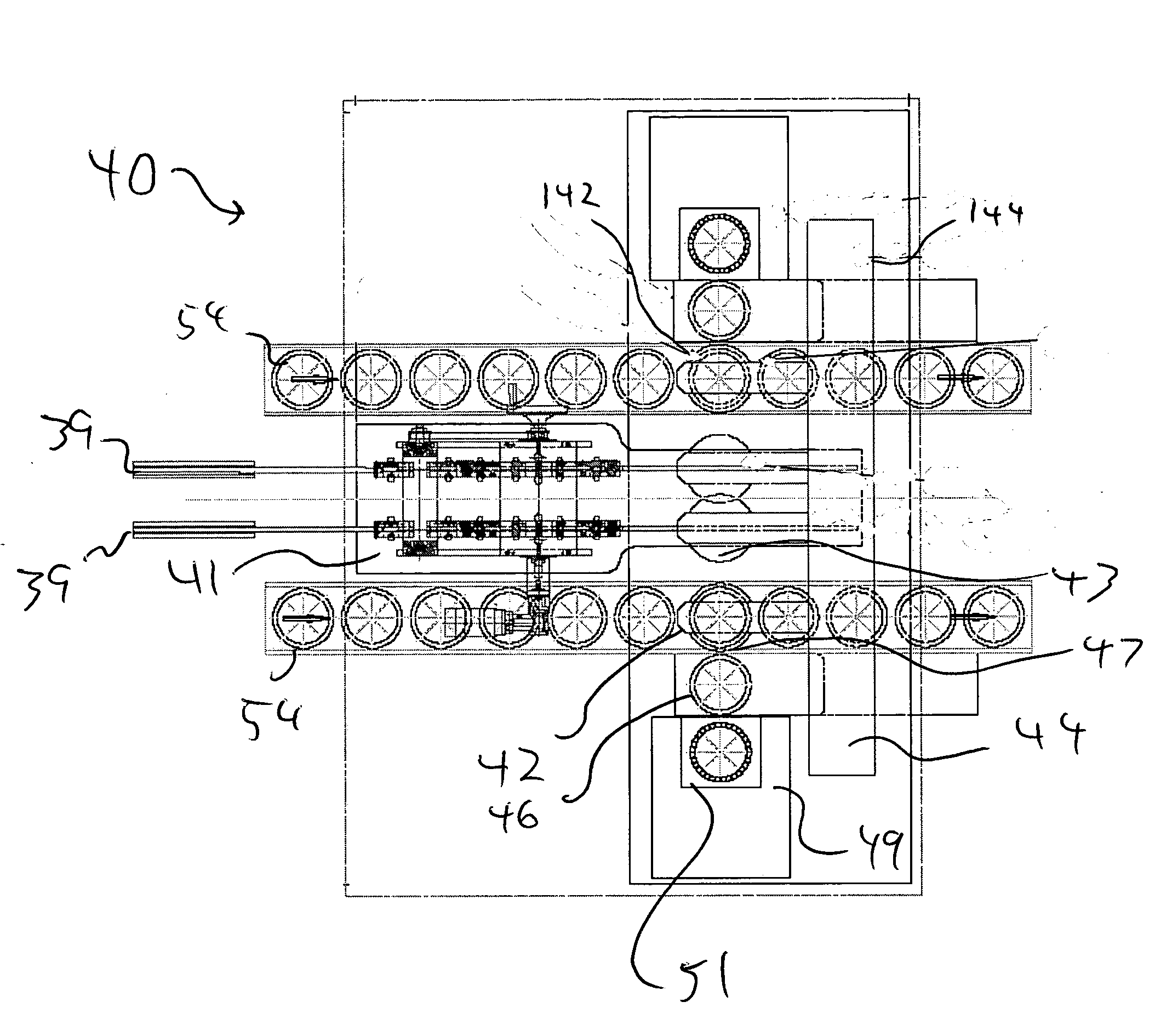
[0008] A method and system in accordance with the principals of the present invention assembles clutch plate assemblies in a more efficient and robust manner.

Problems solved by technology

A disadvantage of the prior art process is that many segments are required to assemble each clutch plate.
This speed is attainable, but creates many challenges in the areas of machine troubleshooting, machine maintenance, and robustness of machine longevity, for example.
Another disadvantage of the prior art is the removal and reinsertion of the one-sided assembly in order to produce a final two-sided assembly.

Method used


Image

  • Assembly process for scrapless clutch plate assembly
  • Assembly process for scrapless clutch plate assembly
  • Assembly process for scrapless clutch plate assembly

Examples


Embodiment Construction

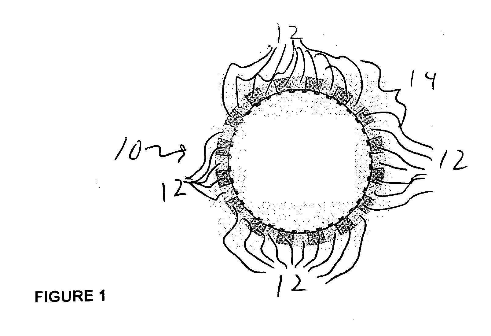
[0012] Referring to FIG. 1, segmented clutch material 10 is seen. The segmented clutch material 10 includes a plurality of segments 12 placed side-by-side to form a circular ring of material 14. The segments 12 are preferably trapezoidal shaped. The assembly process of the prior art calls for placing a single segment into one of a series of nest machined into a rotating ring. After each segment is placed (or pushed) into its nest the ring of nests is rotated so that the next segment may be placed into a nest. This is the process that results in many segments being required to assemble each clutch plate thus requiring very low cycle times for each segment placement in order to achieve a reasonable assembly rate for the complete assembly.

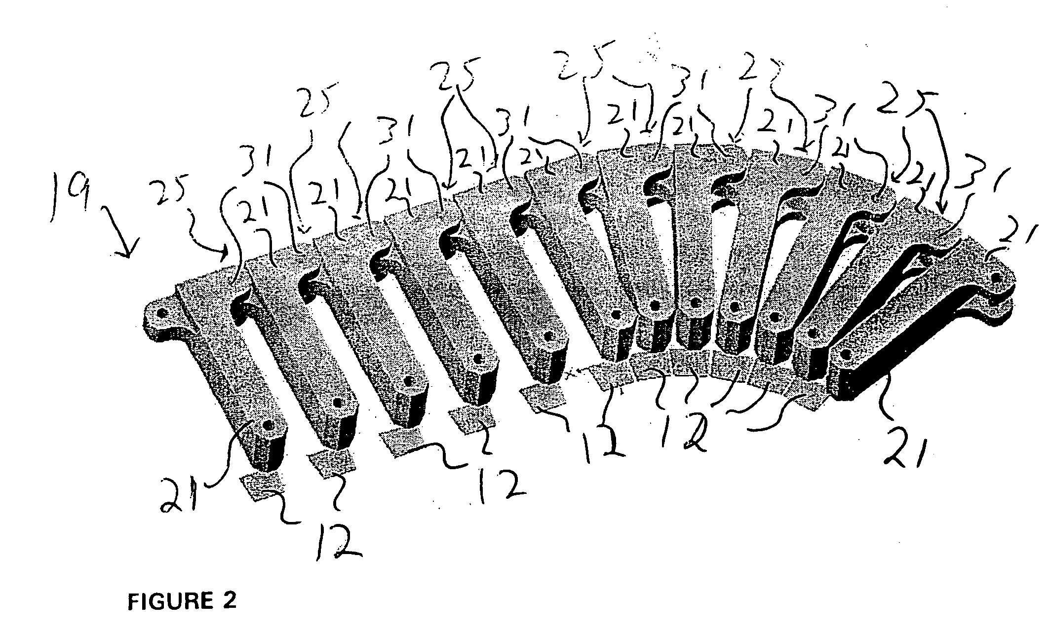
[0013] Referring to FIG. 2, a segmented tooling assembly 19 is seen. The segmented tooling assembly 19 includes a plurality segments tools 21. Each of the segment tools 21 is joined at a pivot point 25 that comprises a pin assembly 31. Numerous metho...


PUM


Abstract

The present invention relates to the assembly of the type of clutch plate referred to as “scrapless”. A method and system in accordance with the principals of the present invention assembles clutch plate assemblies in a more efficient and robust manner. A method and system in accordance with the principals of the present invention provides for a segmented tooling assembly that can be both linear and circular.

Description

FIELD OF THE INVENTION [0001] The present invention relates to the assembly of the type of clutch plate referred to as “scrapless”. BACKGROUND OF THE INVENTION [0002] Prior art clutch plates use a flat ring of a fabric-like clutch material bonded to one or both sides of a metal ring. This metal ring has a spline on its inside diameter to transfer the torque placed on the clutch. The ring of clutch material is cut from a strip of the material, leaving a certain amount of scrap to be disposed of. In contrast, the “scrapless” type of clutch uses trapezoidal shaped segments placed side-by-side to form a circular interrupted ring of the material. [0003] In the prior art, the trapezoidal segments are placed in a nest and then the steel ring is placed on top of the segments. The segments are then bonded to one side of the steel ring by means of pressure and heat. The ring and segments are then removed from the assembly nest, a second set of segments are placed in the nest. The ring must th...

Claims


Application Information

Patent Timeline
IPC IPC(8): F16D13/64
CPCF16D13/64Y10T29/49828F16D2250/00F16D13/648B23P15/00B23P19/04B23P11/00
Inventor TERPSTRA, PAUL D.
Owner GILMAN ENG & MFG
Learn More