Ultrasonic gas flowmeter as well as device to measure exhaust flows of internal combustion engines and method to determine flow of gases

a gas flowmeter and ultrasonic technology, applied in the direction of indirect mass flowmeters, measurement devices, instruments, etc., can solve the problem of difficult construction of capacitive transducers, and achieve the effect of improving capacities

Active Publication Date: 2005-03-31
AVL LIST GMBH
View PDF2 Cites 49 Cited by
  • Summary
  • Abstract
  • Description
  • Claims
  • Application Information

AI Technical Summary

Benefits of technology

This object is achieved according to the invention in that the sound transducers are designed as capacitive ultrasonic transducers for the generation of sound as well as for the reception of time transient sound signals, and devices to level the gas temperature profile of the flow, and to minimize the influence of the temperature profile on the flow measurement.
It can be further proposed to increase precision in that the precise start of the reception signal is determined with the aid of a first noisy phase position based on the estimated time for the start of the reception signal.

Problems solved by technology

However, the through-going electric conductivity of the diaphragm material makes the construction of the capacitive transducer more difficult.

Method used


Image

  • Ultrasonic gas flowmeter as well as device to measure exhaust flows of internal combustion engines and method to determine flow of gases
  • Ultrasonic gas flowmeter as well as device to measure exhaust flows of internal combustion engines and method to determine flow of gases
  • Ultrasonic gas flowmeter as well as device to measure exhaust flows of internal combustion engines and method to determine flow of gases

Examples


Embodiment Construction

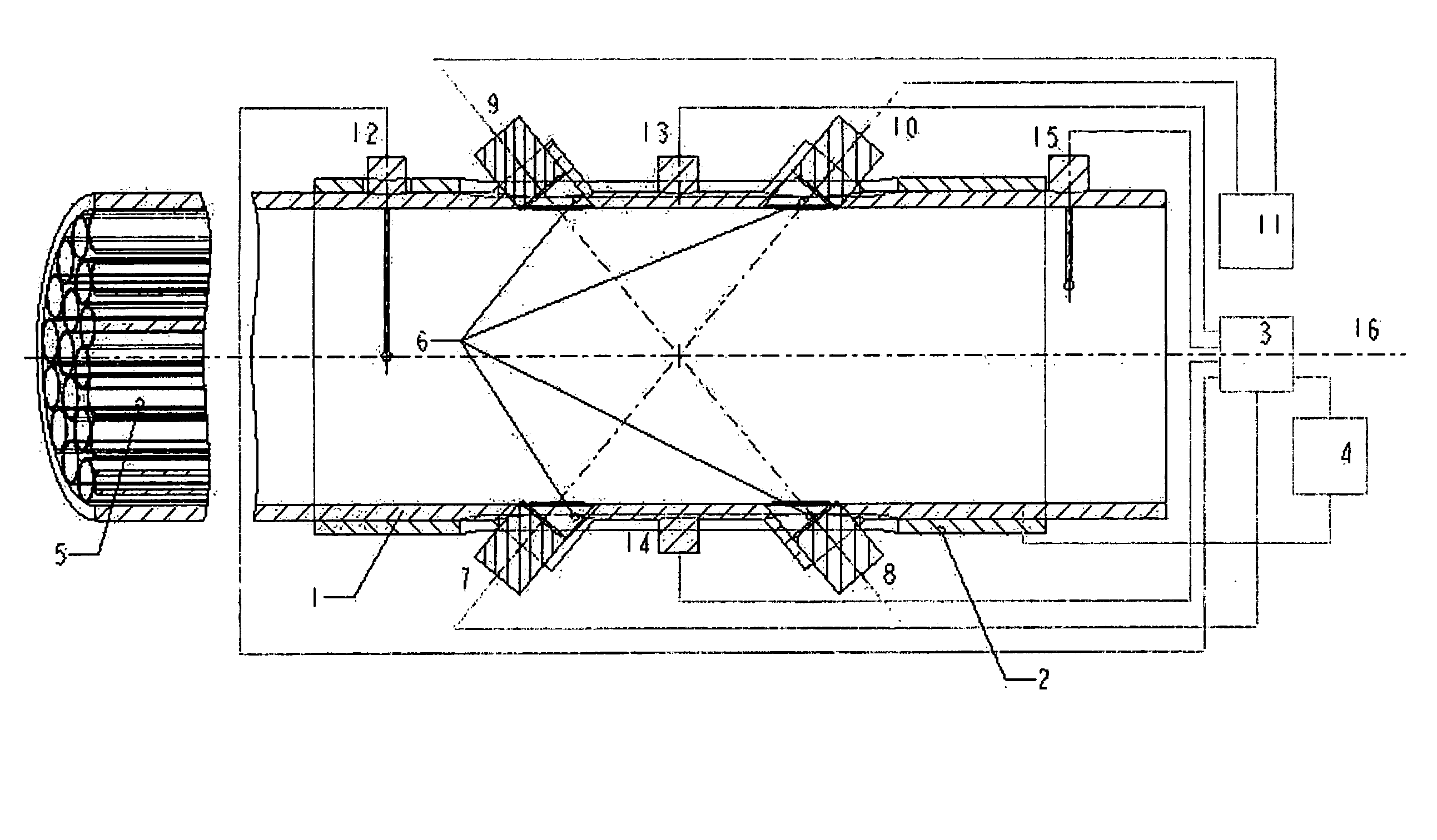
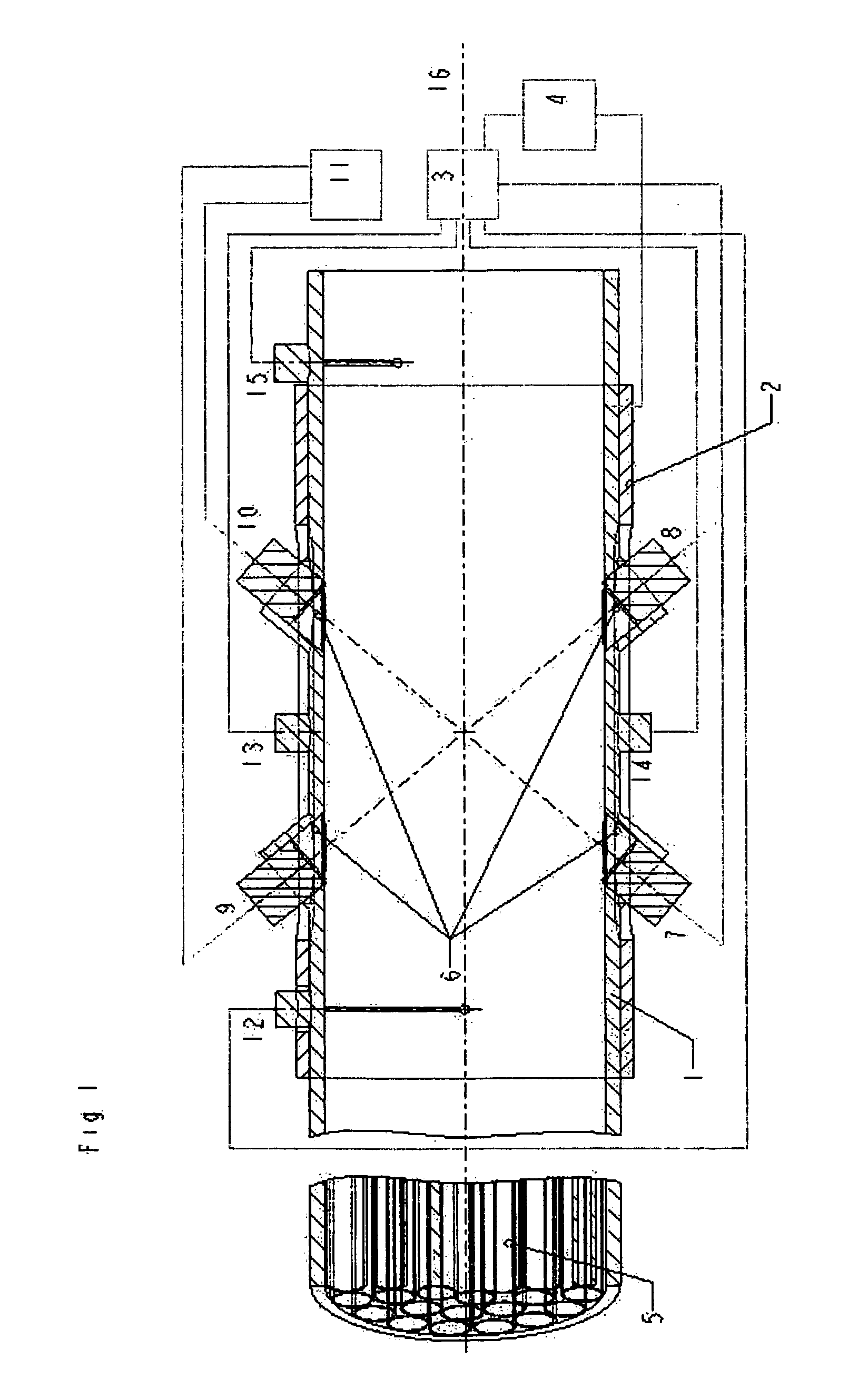
The longitudinal section of the inventive gas flowmeter arrangement of FIG. 1 shows the measuring pipe 1 through which the gas flows whose volume or mass it to be determined. The measuring pipe 1 is provided with a heating element 2 with which the temperature of the measuring pipe 1 can be increased and controlled via the evaluation electronics 3 while interconnected to heating control electronics 4. The measuring pipe is advantageously equipped with additional flow and temperature profile-forming baffles 5 in front of the location of the transit time measurement (relative to the direction of the main flow through the pipe.) These baffles 5 may be designed as guiding metal foils or bundles of tubing having a smaller diameter than the measuring pipe 1.

The transmission transducers 7 and 8 as well as the reception transducers 9 and 10 are inserted in the pockets or lateral cylindrical pieces of the measuring pipe, which can be closed off by the acoustically-transmissive full covers ...


PUM


Abstract

An ultrasonic gas flowmeter includes a measuring pipe with flowing gas, transmitting and receiving sound transducers, transmission and reception electronics, and evaluation electronics. The sound transducers (7, 8, 9, 10) are designed as capacitive electro-acoustic ultrasonic transducers to construct a flowmeter with improved capacity, especially in view of temperature stability and the reduction and consideration of a temperature profile. Devices (5, 6) are provided to level the gas temperature profile and to minimize the influence of the temperature profile on the flow measurement. A more accurate and dependable detection of the volume flow or the mass flow of gases is to be achieved, especially in highly dynamic flows, for the method of determining the flow of gases whereby the mean flow velocity is determined and the flowing gas quantity is determined with highly synchronized resolution from the two transit times of two acoustic signals. In addition, an assessed value is computed (35) for the flow after the determination of the transit times and the assessed value is corrected at least by means of a characteristic temperature of the gas and the temperature of the wall of the measuring pipe (36).

Description

BACKGROUND OF THE INVENTION 1. FIELD OF THE INVENTION The invention relates to an ultrasonic gas flowmeter including at least one transmitting sound transducer, one receiving sound transducer, transmission and reception electronics, and a device to measure exhaust flows of internal combustion engines, as well as a method to determine the flow of gases whereby the mean flow velocity is determined and whereby the flowing quantity of gas is also determined with a highly synchronized resolution from the transit time of the acoustic signals between transmitter and receiver. 2. THE PRIOR ART Such ultrasonic flowmeters are known for fluids and gases and they are the subject of various publications and professional articles. They use the so-called dragging effect, namely in that the velocity in the direction of the beam of acoustic signals in fluids is not only determined by the orientation of the acoustic transmitter and the sound velocity of the (static) medium, but these acoustic sig...

Claims


Application Information

Patent Timeline
Patent Type & Authority Applications(United States)
IPC IPC(8): G01F1/00G01F1/66G01F15/02
CPCG01F1/662G01F15/024G01F1/668G01F1/667
Inventor KUPNIK, MARIOSCHRODER, ANDREASWIESINGER, MICHAELHARMS, KLAUS-CHRISTOPH
Owner AVL LIST GMBH
Why Eureka
Try Eureka