
Method for producing an aluminum alloy composite material for a heat exchanger, and aluminum alloy composite material

a technology of composite materials and heat exchangers, which is applied in the direction of layered products, chemistry apparatuses and processes, metal layered products, etc., can solve the problems of defective brazing, reduced amount of filler alloys to be supplied, and decreased pressure resistance of heat exchangers

Inactive Publication Date: 2005-03-31
FURUKAWA SKY ALUMINUM CORP
View PDF7 Cites 33 Cited by
  • Summary
  • Abstract
  • Description
  • Claims
  • Application Information

AI Technical Summary

Benefits of technology

[0007] Other and further features and advantages of the present invention will appear more fully from the following description, taken in connection with the accompanying drawing.

Problems solved by technology

Since diffusion of the filler alloy results in a decreased amount of the filler alloy to be supplied to the portion to be brazed, defective brazing, such as discontinuous brazing in a brazed portion (defect owing to insufficient supply of filler alloy) and decrease of pressure resistance of a heat exchanger, may occur.
In addition, the strength and corrosion resistance that the core alloy inherently possesses are largely decreased at the diffusion area of the filler alloy into the core alloy, and the performance of the heat exchanger after heating for brazing is considerably decreased.
However, in this case, such a problem arises as formability of the resulting alloy is decreased due to work hardening caused by applying a strain, and cracks are occurred in the forming process.
Therefore, such countermeasures are far from satisfactory.

Method used


Image

  • Method for producing an aluminum alloy composite material for a heat exchanger, and aluminum alloy composite material
  • Method for producing an aluminum alloy composite material for a heat exchanger, and aluminum alloy composite material

Examples


example

[0045] The present invention is described in more detail hereinafter with reference to examples and comparative examples, however the present invention is by no means limited to these examples.

[0046] An aluminum alloy for a core alloy having a composition of 0.25% of Si, 0.5% of Fe, 0.15% of Cu and 1.1% of Mn with the balance being Al, and JIS 4045 alloy for a filler alloy were cast using a casting mold, respectively. The core alloy was homogenized under a condition with a temperature and a keeping time as shown in Table 1, and was finished to a thickness of 40 mm by scalping. Regarding the filler alloy, the ingot was machined by scalping, hot rolled, and was fitted to both sides of the core alloy with a clad ratio of 10% on each side. The resultant fitted alloys were heated to 500° C., hot-rolled to a thickness of 3.5 mm, and cold rolled to form a triple layer clad material with a thickness of 0.5 mm.

[0047] The cold rolled alloys above were subjected to intermediate annealing as ...


PUM

PropertyMeasurementUnit
temperatureaaaaaaaaaa

Abstract

A method for producing an aluminum alloy composite material for a heat exchanger, which contains the steps of: homogenizing an aluminum alloy core alloy by keeping at 530° C. or more for 15 hours or more; fitting an Al—Si-series filler alloy on one side or on both sides of the core alloy; hot rolling; cold rolling; intermediate annealing, to completely recrystallize the core alloy; and giving a strain of 1 to 10%, wherein the aluminum alloy core alloy contains 0.01 to 1.0% by mass of Si, 0.1 to 2.0% by mass of Fe, 0.1 to 2.0% by mass of Cu, 0.5 to 2.0% by mass of Mn, and less than 0.2% by mass (including 0% by mass) of Ti, with the balance being Al and inevitable impurities; and an aluminum alloy composite material produced by the method.

Description

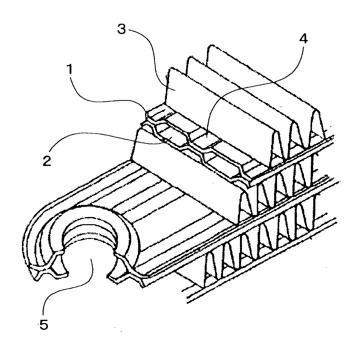
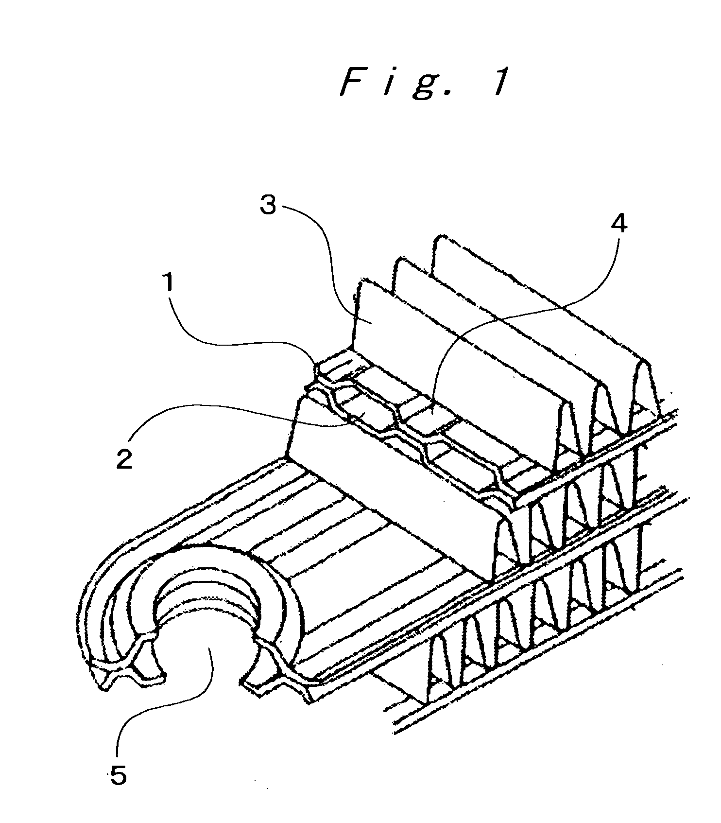
TECHNICAL FIELD [0001] The present invention relates to a method for producing an aluminum alloy composite material for a heat exchanger. Further, the present invention also relates to an aluminum alloy composite material produced by the method. BACKGROUND ART [0002] In general, cores of heat exchangers, such as evaporators and condensers, are manufactured, for example, as shown in FIG. 1, by steps comprising: press-forming a composite material (brazing sheet), which is made up from an aluminum alloy core alloy being clad with a filler alloy on its both surfaces, to form corrugation; stacking the corrugated two sheets of refrigerant passage-forming members 1, to form refrigerant passageways 2 in the longitudinal direction; and then brazing these sheets. In the figure, reference numeral 3 denotes a corrugated fin; reference numeral 4 denotes a brazed joint (flat portion), and reference numeral 5 denotes a refrigerant passageway running in the vertical direction. Since the sheet thick...

Claims


Application Information

Patent Timeline
Patent Type & Authority Applications(United States)
IPC IPC(8): B32B15/01C22C21/00C22C21/14C22F1/00C22F1/04C22F1/057
CPCB32B15/016C22C21/00C22F1/057C22F1/04C22C21/14
Inventor TANAKA, SATOSHIYANAGAWA, YUTAKADOKO, TAKEYOSHI
Owner FURUKAWA SKY ALUMINUM CORP
Learn More