

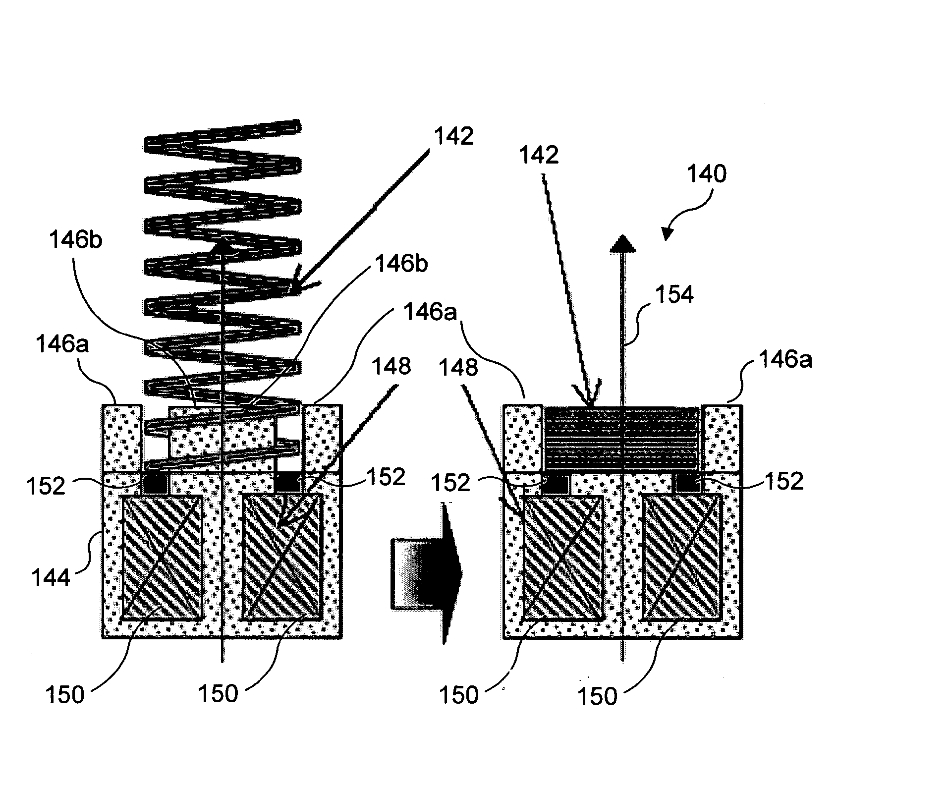
Design of ferromagnetic shape memory alloy composites and actuators incorporating such materials
a technology of shape memory alloys and composite materials, applied in the field of ferromagnetic, can solve problems such as the failure of actuators to perform
- Summary
- Abstract
- Description
- Claims
- Application Information
AI Technical Summary
Benefits of technology
Problems solved by technology
Method used
Image

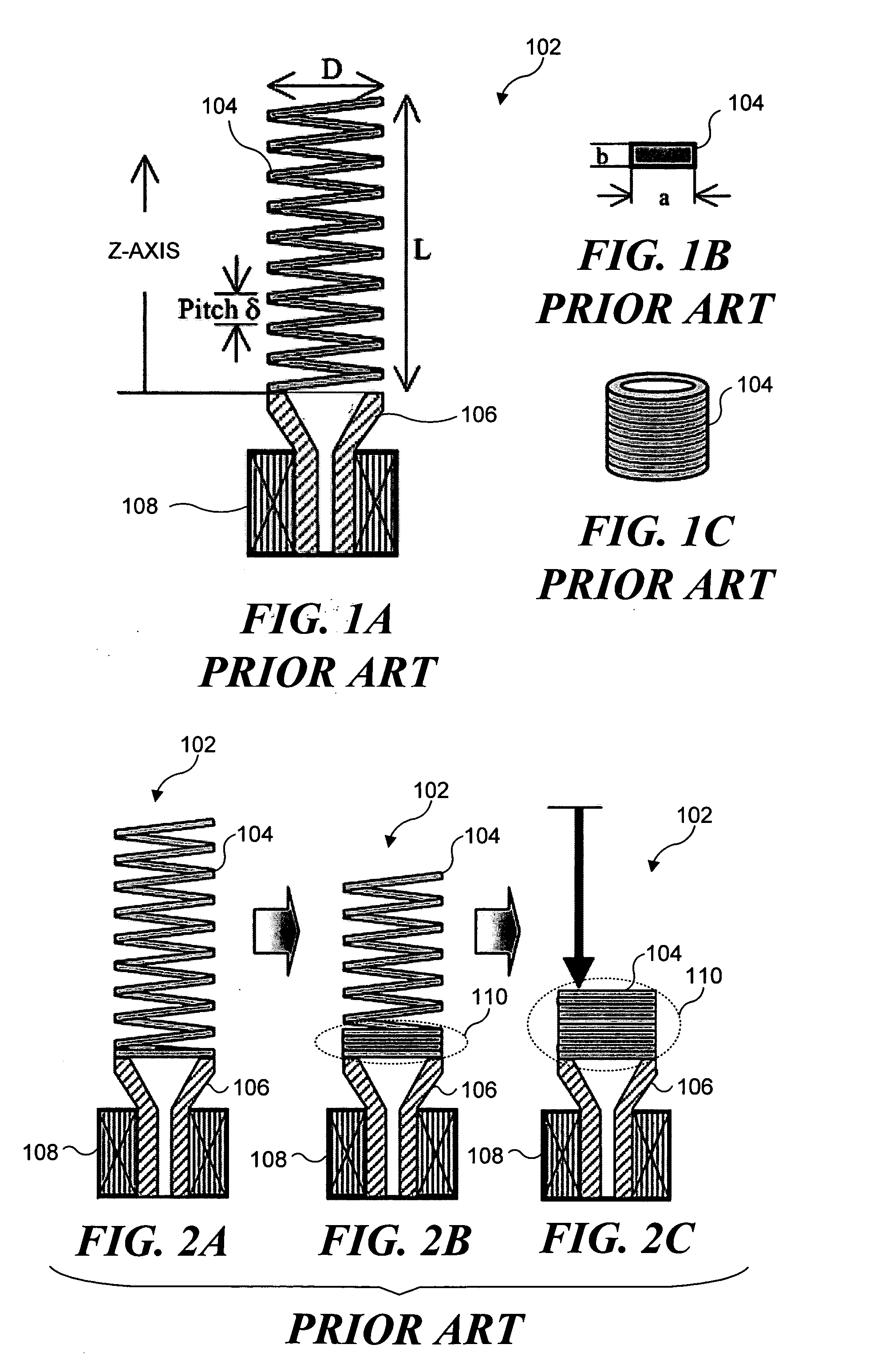
Examples
case 1
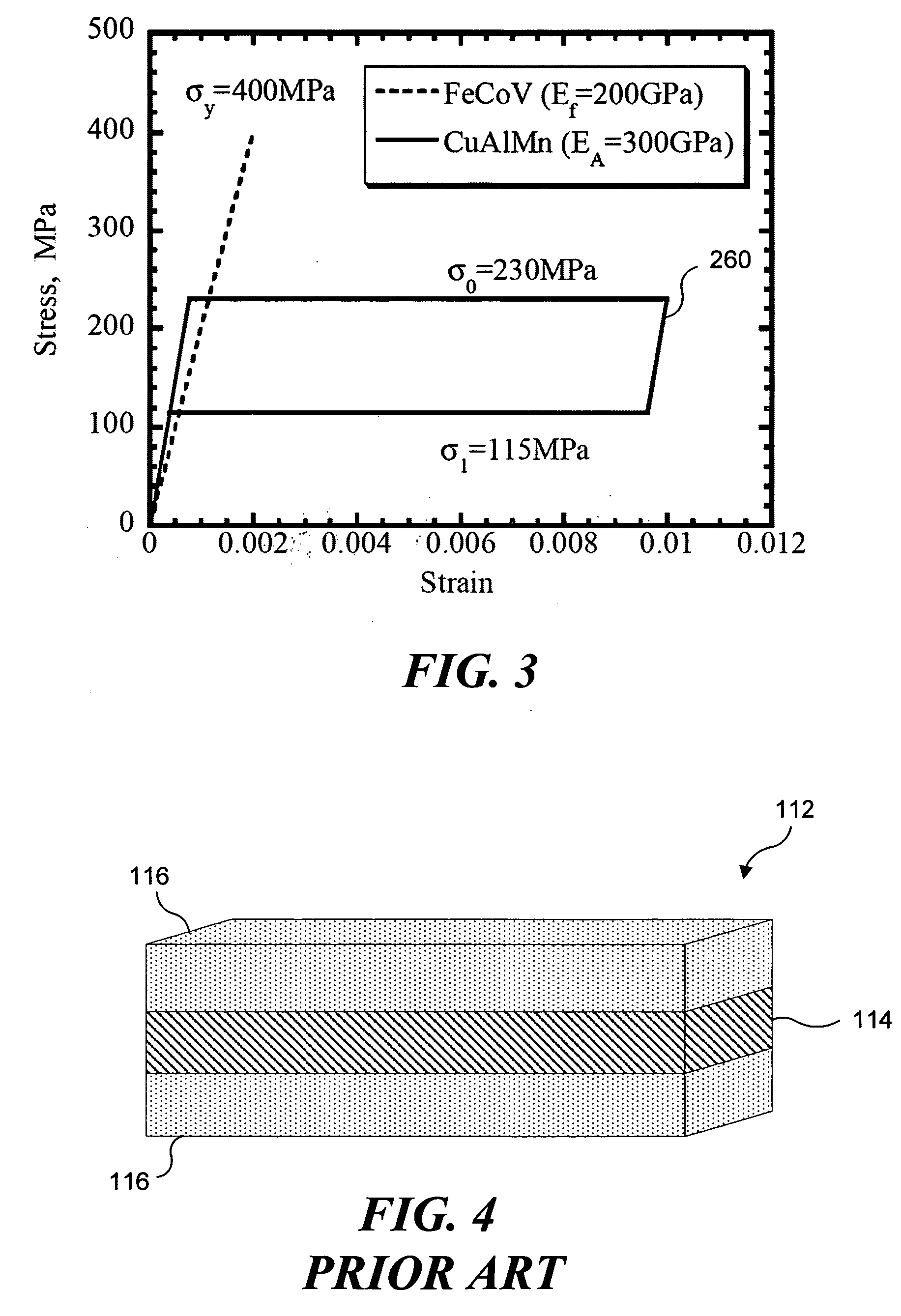
ress in the ferromagnetic layer reaches the yield stress, σf, before reaching the transformation stress,σ0, in the super elastic SMA layer. The stress distribution of this case upon loading and unloading is shown in FIG. 26A, where bending stress by elastic deformation is generated in each material.
case 2
ress in the ferromagnetic layer reaches the yield stress after the SMA layer reaches the transformation stress in the plate. The stress distribution of Case 2 upon loading and unloading is shown in FIG. 26B. Under an increasing bending moment, a first elastic stress distribution is indicated in portion (a) of the Figure, the stress in the SMA layer then reaches the transformation stress, σ0, to the position of y1 in portion (b). When the transformation domain advances to where y1=Y1, the ferromagnetic layer reaches the yield stress, σf, as indicated in portion (c). During unloading, the stress decreases first inelastically in all domains, as indicated in portion (d). The stress then becomes constant in the upper part of the SMA layer to a position y3, where the stress reaches the reverse transformation stress, σ1, as indicated in portion (e). Once the stress at location y3=Y1 reaches σ1, the stress inside portion y<y2 decreases elastically, as indicated in portion (f). Finally,...
case 3
ress in the ferromagnetic layer reaches the yield stress, after the entire domain of the super elastic SMA layer reaches the transformation stress, σ0. The stress distribution of Case 3 upon loading and unloading is shown in FIG. 26C. In the early stage of loading, the stress in the ferromagnetic layer does not reach the yield stress, even after the stress in all domains of the SMA layer reach the transformation stress, σ0, as indicated in portion (c). A neutral axis position changes with an increase in the load, and the stress reaches the yield stress, σf, in the ferromagnetic layer, as indicated in a portion (d). The unloading stresses are illustrated in portions (e)-(h).
For each stress distribution, σx(y), in the three cases discussed above, the following equations are valid (i.e., for defining the equilibrium of force and moment):
∫0hσx(y)ydy=0 (30)
M=−∫0hσx(y)ybdy=0 (31)
The neutral axis position and the relationship between the bending moment and the curvature are obtained...
PUM
| Property | Measurement | Unit |
|---|---|---|
| stress and strain relationship | aaaaa | aaaaa |
| height | aaaaa | aaaaa |
| height | aaaaa | aaaaa |
Abstract
Description
Claims
Application Information