
Synthetic resin part, synthetic resin assembly and method for manufacturing the same

a technology of synthetic resin and parts, applied in the field of synthetic resin parts, synthetic resin assembly and manufacturing the same, can solve the problems of increased inspection steps, increased labor and a long time period, and welding erroneously passing inspections, etc., and achieves the effect of short separation distance, easy inspection, and easy visual inspection

Inactive Publication Date: 2005-03-31
BROTHER KOGYO KK
View PDF7 Cites 3 Cited by
  • Summary
  • Abstract
  • Description
  • Claims
  • Application Information

AI Technical Summary

Benefits of technology

[0006] It is an object of the invention to determine the welding degree after two synthetic resin parts are welded together by a simple and sure method, thereby reducing the number of inspection steps relating to the welding degree, and surely eliminating a synthetic resin assembly of defective welding.
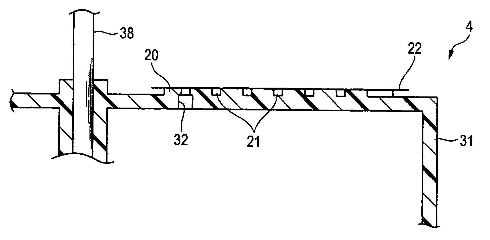
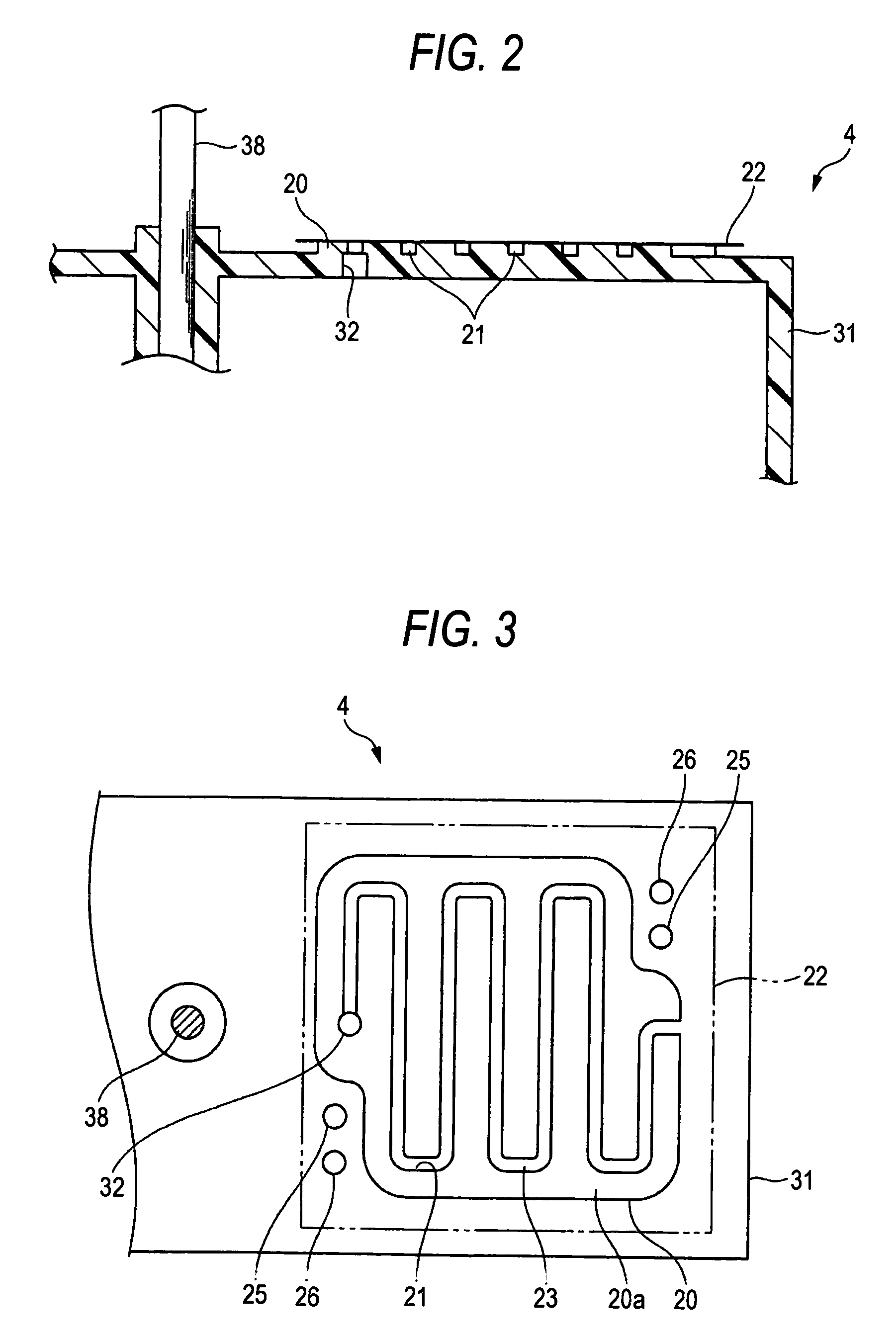
[0019] According to still another aspect of the invention, there is provided a synthetic resin assembly including: a synthetic resin-made container which stores an ink to be supplied to an inkjet head; and a synthetic resin-made film which is welded to the container; wherein the container has: a weld surface which is to be welded to the film; and two projections in which positions of tops are lower in level than the weld surface, and different from each other; and the top of one of the two projections which has a shorter separation distance from the weld surface is welded to the film, and the top of another one of the two projections which has a longer separation distance from the weld surface is not welded to the film. Therefore, it is possible to easily check by visual inspection or the like whether the welding degree of the film welded to the container is adequate or not.

Problems solved by technology

When such a leakage inspection, a destructive inspection, and the like are conducted on all synthetic resin assemblies, much labor and a prolonged time period are required, and the number of inspection steps is increased.
When such inspections are conducted by a sampling method, there is the possibility that a synthetic resin assembly of defective welding erroneously passes the inspections to be shipped as it is.

Method used


Image

  • Synthetic resin part, synthetic resin assembly and method for manufacturing the same
  • Synthetic resin part, synthetic resin assembly and method for manufacturing the same
  • Synthetic resin part, synthetic resin assembly and method for manufacturing the same

Examples


Embodiment Construction

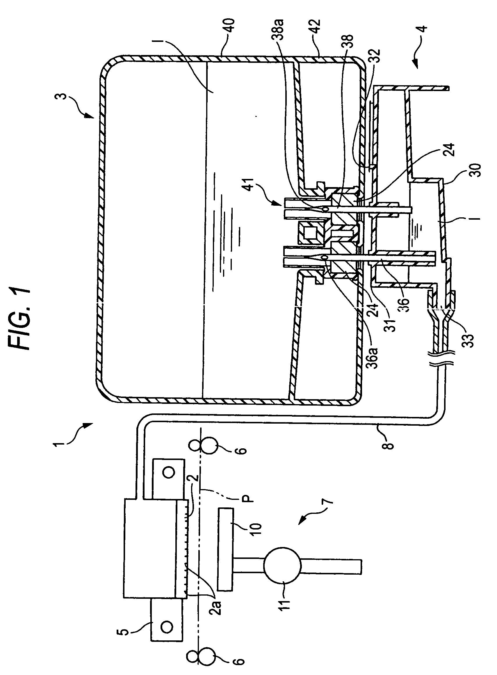
[0032] An embodiment of the invention will be described. In the embodiment, the invention is applied to an ink cartridge and an inkjet printer to which the ink cartridge is to be attached.

[0033] First, an inkjet printer 1 to which an ink cartridge 3 is to be attached will be described.

[0034] As shown in FIG. 1, the inkjet printer 1 has: an ink-jet head 2 having nozzles 2a from which an ink I is ejected toward a recording sheet P; a buffer tank 4 which is connected to the inkjet head 2 via a supply tube 8, and which retains the ink I flowing from an ink cartridge 3 that is attached above the buffer tank; a carriage 5 which linearly moves the inkjet head 2 in one direction in a reciprocal manner; a transporting mechanism 6 which transports the recording sheet P; and a purging device 7 which sucks air bubbles in the inkjet head 2 and the thickened ink I.

[0035] In the inkjet printer 1, the ink I is supplied from the buffer tank 4 to which the ink cartridge 3 is attached, to the nozzl...


PUM

PropertyMeasurementUnit
separation distancesaaaaaaaaaa
transparentaaaaaaaaaa
separation distanceaaaaaaaaaa

Abstract

A synthetic resin part has plural welding degree checking portions which are lower in level than a weld surface thereof and separated from the weld surface by different separation distances. When the synthetic resin part is welded in the weld surface to another synthetic resin part, a degree of the welding is determined based on a state whether each of the welding degree checking portions is welded to the other synthetic resin part or not.

Description

BACKGROUND OF THE INVENTION [0001] 1. Field of the Invention [0002] The present invention relates to a technique for checking the welding degree of two synthetic resin parts which are welded together to constitute a synthetic resin assembly. [0003] 2. Description of the Related Art [0004] Usually, a synthetic resin assembly configured by plural synthetic resin-made parts; such as an ink cartridge which can store an ink to be supplied to an inkjet head, is assembled by welding the synthetic resin-made parts together by various welding methods such as heat welding and ultrasonic welding (for example, see JP-A-2000-43285 (Page 4, FIG. 1)). When the two synthetic resin parts to be welded together are welded in an insufficient amount, or contrarily in an excess amount, there arise the possibilities that the sealing property of the welded portion which must be sealed cannot be sufficiently ensured, and that the strength of the welded portion is insufficient. Conventionally, therefore, two...

Claims


Application Information

Patent Timeline
Patent Type & Authority Applications(United States)
IPC IPC(8): B29C65/00B29C65/02B29C65/08B29C65/82B41J2/175
CPCB29C65/08B29C66/30223B29C66/54B29C66/97B29L2031/767B41J2/17513B29C66/53461B41J2/17559B29C66/534B29C65/8246B29C65/8253B29C66/8322B41J2/17523B29C66/61B29C66/112B29C66/1122B29C66/131
Inventor KATAYAMA, NAOKI
Owner BROTHER KOGYO KK
Learn More