Load-Resistant Coaxial Transmission Line

a transmission line and load-resistant technology, applied in the direction of cables, insulated conductors, borehole/well accessories, etc., can solve the problems of impracticality of exclusive gaseous system and transmission line cables that have been proposed in the art have not been designed for harsh environments, etc., to achieve high electrical conductivity and improve electrical conductivity

Active Publication Date: 2005-03-31
INTELLISERV
View PDF99 Cites 167 Cited by
  • Summary
  • Abstract
  • Description
  • Claims
  • Application Information

AI Technical Summary

Benefits of technology

[0017] This disclosure presents a semi-rigid transmission line for downhole tools that are associated in a drill string, tool string, bottom hole assembly, or in a production well. The downhole tools, in reference to a drill sting, are joined together at tool joints, and in order to transmit information and power along the tool string, it is necessary to provide a transmission system that includes means for bridging the connected tool joints and a transmission line that is capable of elongation, that is impervious to abrasive fluids, and that is resistant to the dynamic gravitational forces and acceleration ever present in the downhole environment. Such a transmission line is presented herein consisting of tensile components comprising an outer conductor, a dielectric, and an inner conductor. The outer conductor may be a metal tube adapted for high electrical conductivity; the dielectric is preferably a fluoropolymer or a ceramic material hav...

Problems solved by technology

It has long been the unrealized goal of the drilling and subterranean excavation industries to achieve a real time, high data rate transmission of information from the excavation tool to the surface control systems.
But an exclusively gaseous syst...

Method used


Image

  • Load-Resistant Coaxial Transmission Line
  • Load-Resistant Coaxial Transmission Line
  • Load-Resistant Coaxial Transmission Line

Examples


Embodiment Construction

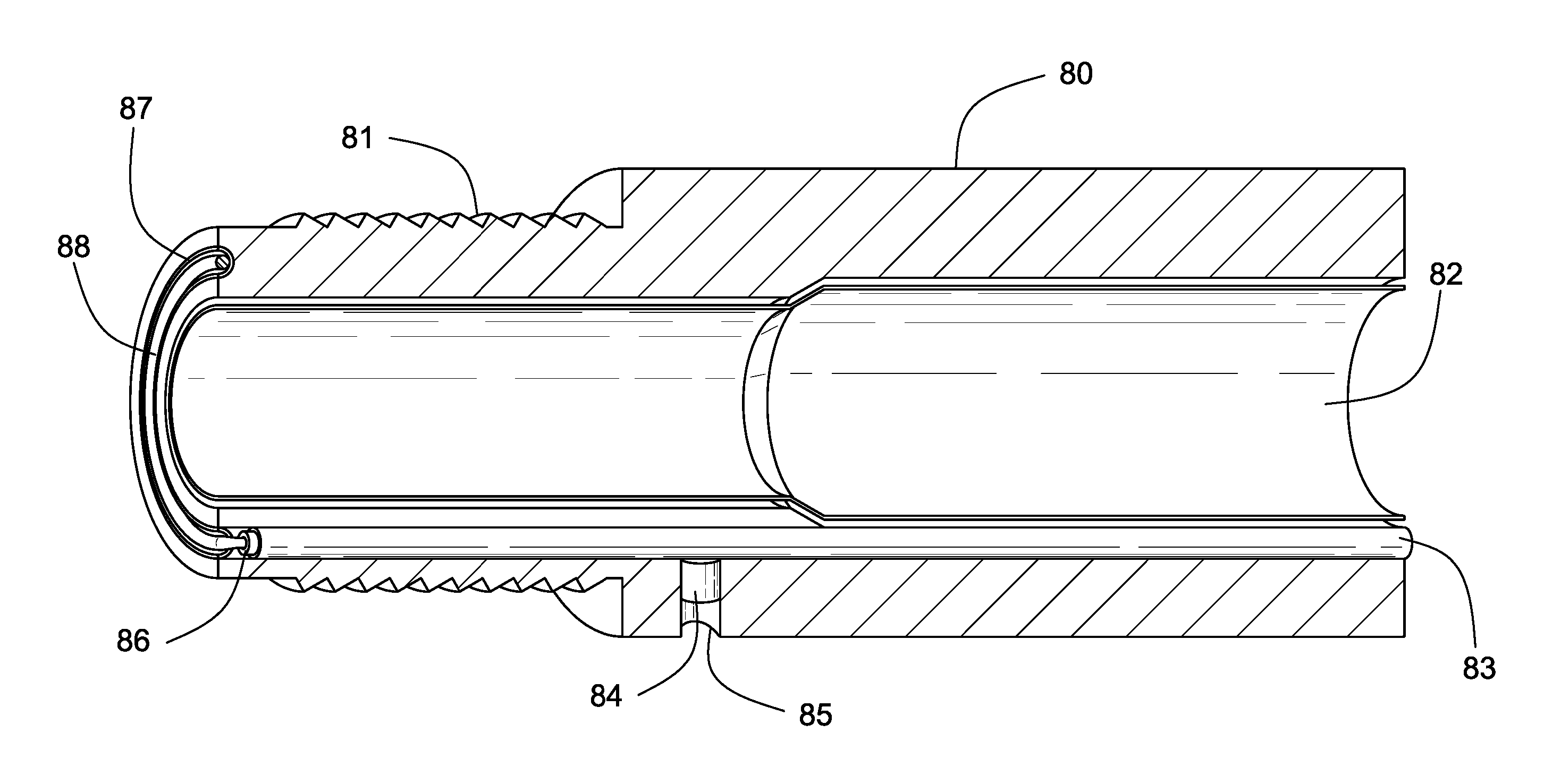
[0026] A tool string for drilling oil, gas, and geothermal wells consists of interconnected sections of downhole tool components associated with drill pipe. The tool string may also comprise coiled tubing, which is a continuous length of tubing. The chief advantage of coiled tubing is that it eliminates the segmented composition of the tool string in so far as it may relate to the drill pipe. However, even in coiled tubing applications, it is necessary to connect up to downhole tools in order to obtain full the utility of the varied downhole tools required to successfully drill a well.

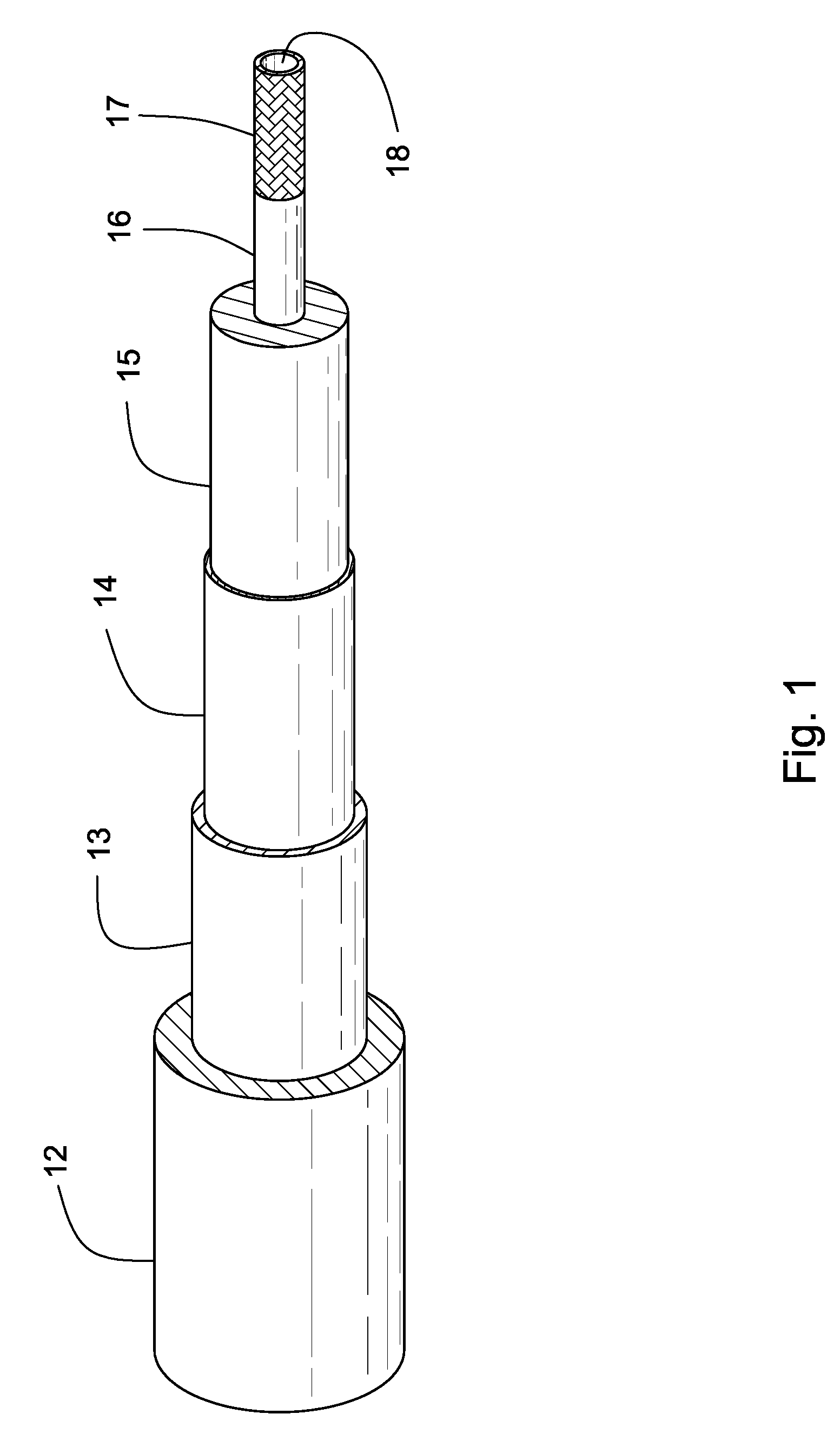
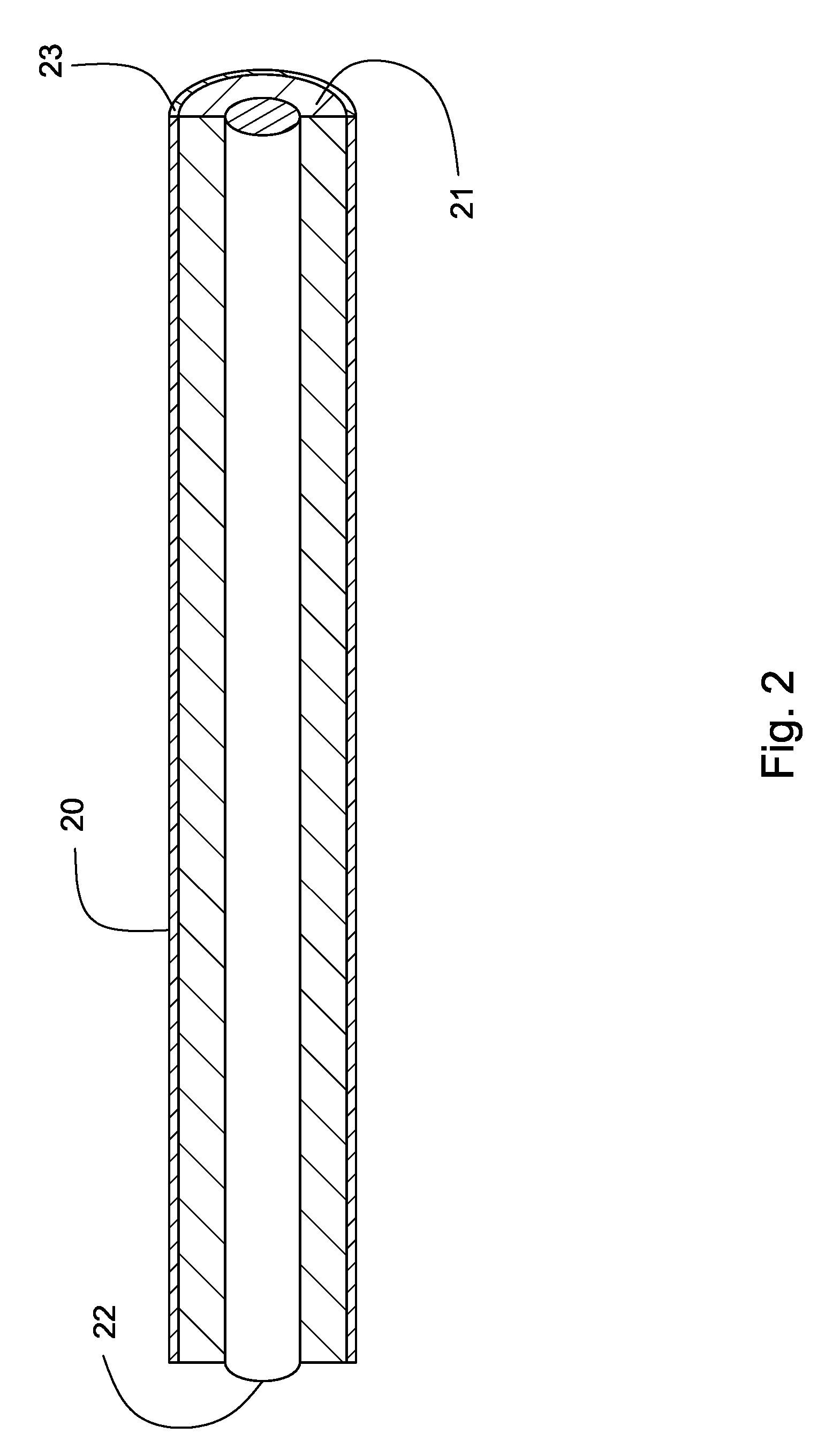
[0027] Whether in a segmented or continuous configuration, a downhole transmission line for transmitting data up and down the tool string must be capable of withstanding the dynamic conditions of drilling. These dynamic conditions include high tensile stresses, due to the suspended mass of the tool string, where the elastic strain is believed to be at least about 0.3%; rapid accelerations associated w...


PUM


Abstract

A transmission line for downhole tools that make up all or part of a tool string for drilling and production of oil, gas, and geothermal wells that can withstand the dynamic gravitational forces and other accelerations associated with downhole excavations. The transmission line comprises a metal tube, or outer conductor, that houses a coaxial wire inner conductor. A non-metallic dielectric material is interposed between the inner and outer conductors. The outer and inner conductors and the dielectric are sufficiently compressed together so that independent motion between them is abated. Compression of the components of the transmission line may be achieved by drawing the transmission through one or more dies in order to draw down the outer conductor onto the dielectric, or by expanding the inner conductor against the dielectric using a mandrel or hydraulic pressure. Non-metallic bead segments may be used in aid of the compression necessary to resist the dynamic forces and accelerations of drilling.

Description

FEDERAL RESEARCH STATEMENT [0001] This invention was made with government support under Contract No. DE-FC26-97FT343656 awarded by the U.S. Department of Energy. The government has certain rights in the invention.BACKGROUND OF INVENTION [0002] 1. Field of the Invention [0003] This disclosure is related to a transmission line for down-hole tools such as are associated with drill pipes in a tool string. More particularly, this disclosure relates to a semi-rigid transmission line that is capable of withstanding the tensile stresses, dynamic accelerations, and gravitational loads experienced by the downhole tools when drilling an oil, gas, or geothermal well. [0004] 2. Description of the Related Art [0005] The transmission line of this disclosure is provided by placing the various components of the transmission line in sufficient contact with each other that independent motion between them is abated during use. [0006] It has long been the unrealized goal of the drilling and subterranean...

Claims


Application Information

Patent Timeline
IPC IPC(8): E21B17/00E21B17/02H01B7/04H01B11/18H01B13/00
CPCE21B17/003E21B17/028H01B13/0006H01B11/1865H01B7/046E21B17/0285
Inventor HALLFOX, JOE
Owner INTELLISERV
Why Eureka
Try Eureka