Oil management system for dual clutch transmissions

a dual clutch transmission and oil management technology, applied in the direction of mechanical actuated clutches, clutches, mechanical apparatus, etc., can solve the problems of difficult to efficiently control the fluid flow for each such function, the associated clutch tends to self-disengage, and the piston pressure within the pressure chamber exerts unwanted pressure on the piston, etc., to achieve more responsive clutches, reduce fluid flow requirements and volumes, and reduce fluid flow.

a dual clutch transmission and oil management technology, applied in the direction of mechanical actuated clutches, clutches, mechanical apparatus, etc., can solve the problems of difficult to efficiently control the fluid flow for each such function, the associated clutch tends to self-disengage, and the piston pressure within the pressure chamber exerts unwanted pressure on the piston, etc., to achieve more responsive clutches, reduce fluid flow requirements and volumes, and reduce fluid flow.

US20050067251A1Inactive Publication Date: 2005-03-31BORGWARNER INC

Image

  • Oil management system for dual clutch transmissions
  • Oil management system for dual clutch transmissions
  • Oil management system for dual clutch transmissions

Examples


Embodiment Construction

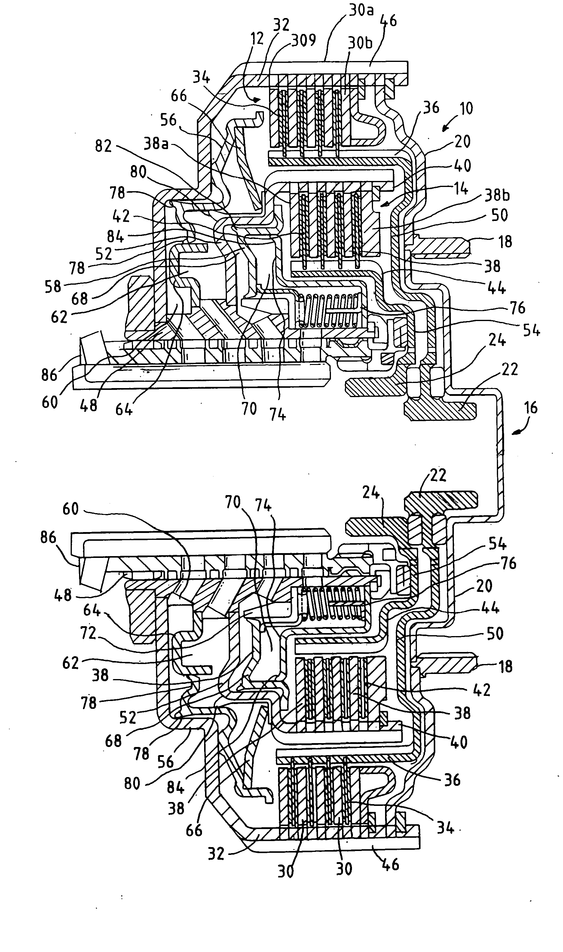
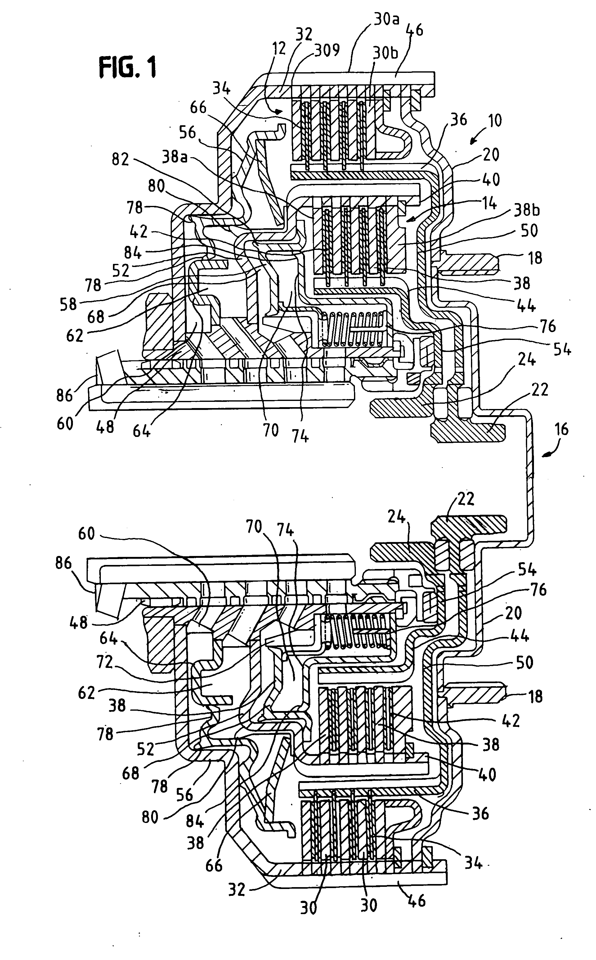
[0037] One aspect of the invention is shown in FIG. 1 as employed in a dual clutch 10 with a first outer clutch disk stack 12 and a second inner clutch disk stack 14. The clutch includes a drive input hub 16 to receive a torque input from an engine draft shaft, fly wheel, torque converter or other engine drive input (not shown). In this example, the drive input hub 16 includes splines 18 to join the torque input source to an outer housing 20, which is operatively connected to the driving disks of the first 12 and second 14 clutch disk stacks.

[0038] A first clutch output spline 22 is operably connected to the driven disks of the first, outer disk stack 12, and a second clutch output spline 24 is operably connected to the driven disks of the second, inner disk stack 14. In a typical application, the second output spline 24 is keyed to a first outer drive shaft to provide driving torque to preselected gears in a gear box (not shown) when the second inner disk stack 14 is actuated. The...


PUM


Abstract

The present invention provides an improved fluid management system for dual and other multiple clutch assemblies having fluid-operated pistons and fluid operated balance chambers offsetting the undesired pressures exerted by fluids within the piston chamber induced by centrifugal forces. Among other improvements, the system provides an effective and cost efficient arrangement of fluid supply channels and supply openings capable of maintaining desired fluid levels in the balance chambers under low, otherwise insufficient, flow rate conditions. In another aspect, the system provides a reservoir for the balance chambers under conditions where the fluid flow is stopped or interrupted.

Description

1. FIELD OF THE INVENTION [0001] The invention relates generally to a clutch mechanism for a transmission utilizing oil or other fluid systems such as those used in automotive dual clutch transmissions. 2. BACKGROUND [0002] One form of automotive transmissions utilizes a dual clutch system to transmit torque to a gear box or other gear shifting mechanism. Such dual clutch systems may be used in manual, an assisted manual or automatic transmissions. Dual clutch systems typically are provided with a single torque input from the engine that is transferred by the clutch to one of a pair of shafts out of the clutch to the transmission gear box. [0003] The torque input is transferred to the output shafts through a pair of selectively engageable, compressible stacks of clutch disks. Such dual clutch systems typically have a first and a second clutch stack, and each stack has a set of driving disks and a set of driven disks. The driving disks are operatively connected to the torque input, a...

Claims


Application Information

Patent Timeline
31 Mar 2005
Publication
US20050067251A1
IPC
F16D21/06; F16D25/0638; F16D25/10; F16D25/12; F16D48/02; F16D48/04; F16H57/04
CPC
F16D21/06; F16D25/0638; F16D25/10; F16D25/123; F16H57/04; F16D48/04; F16D2021/0653; F16D2021/0661
Inventors
BRAFORD, THOMAS E. JR.; GERLACH, MARTIN