Self heating apparatus

a self-heating and heating element technology, applied in the field of heating applications, can solve the problems of large heat loss, many heating elements, and increased complexity and cost, and achieve the effect of reducing the risk of heat loss, and reducing the efficiency of heating elements

Inactive Publication Date: 2005-03-31
GENERAL ELECTRIC CO
View PDF2 Cites 110 Cited by
  • Summary
  • Abstract
  • Description
  • Claims
  • Application Information

AI Technical Summary

Problems solved by technology

However, the use of heating element suffers from many disadvantages.
Addition of a separate heating element into an apparatus or system adds to the complexity and costs.
Further, since the heating element usually generates heat in a concentrated region, and all of this heat is not be absorbed within that region, a large component of the heat may escape to regions where heating is not required, which is undesirable, for example in refr

Method used


Image

  • Self heating apparatus
  • Self heating apparatus
  • Self heating apparatus

Examples


Embodiment Construction

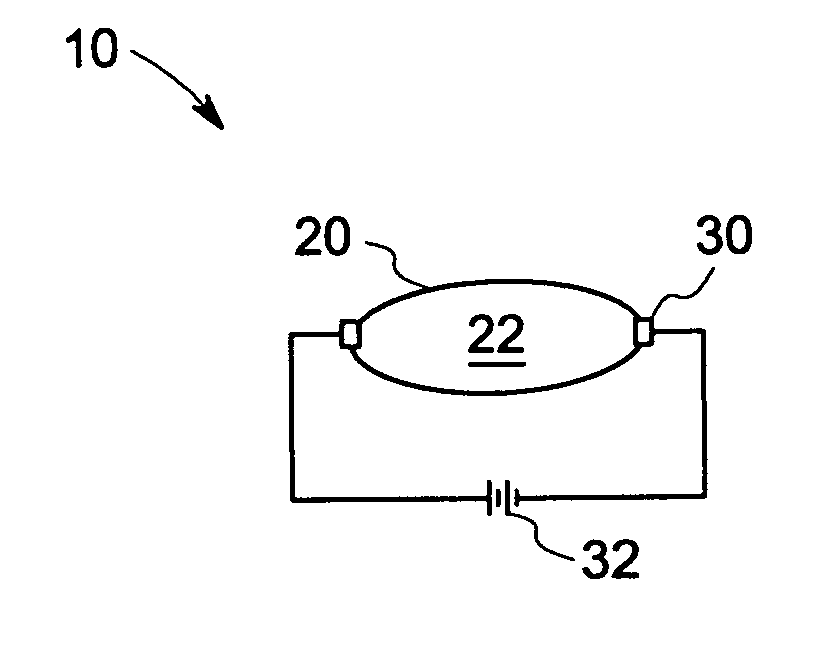
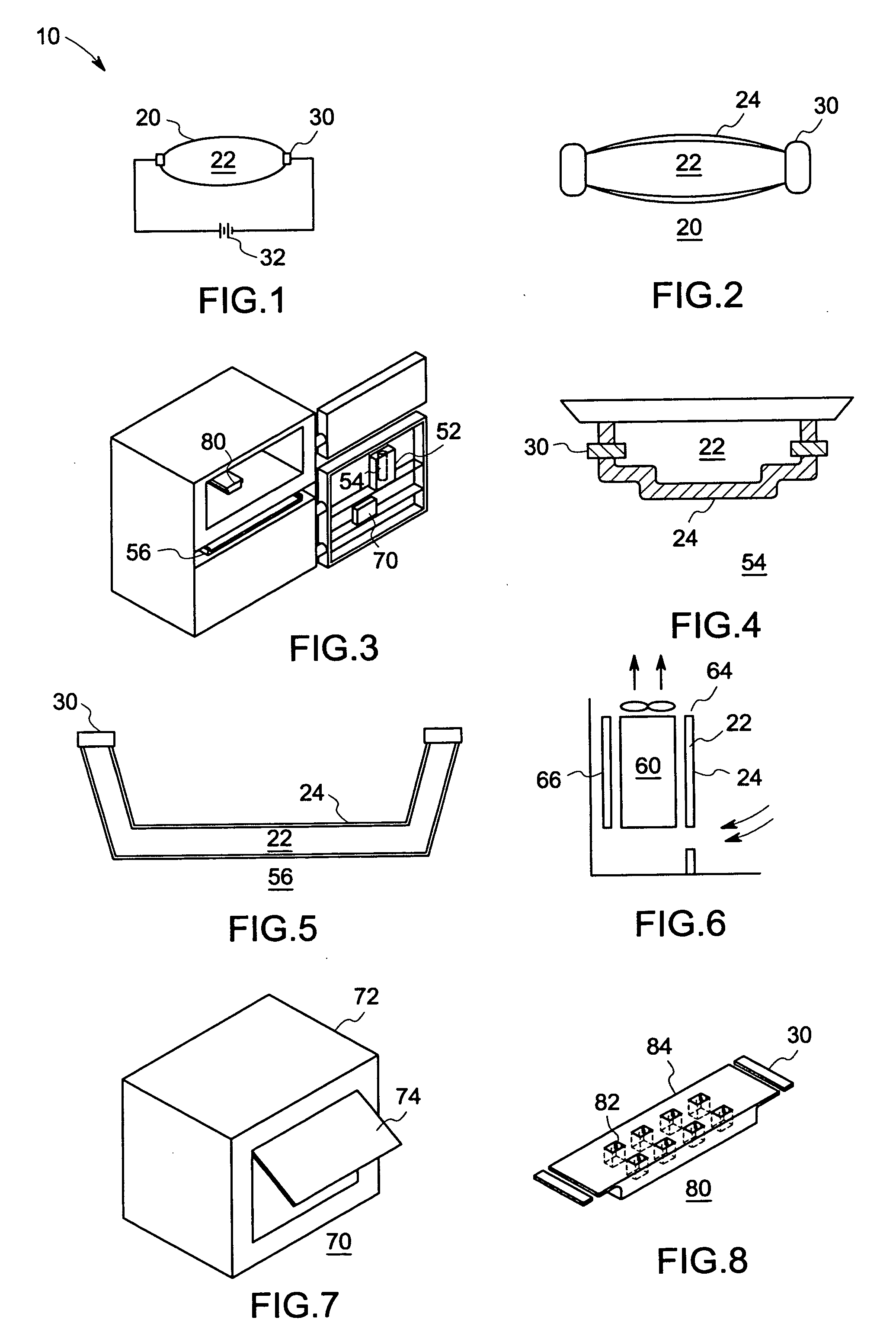
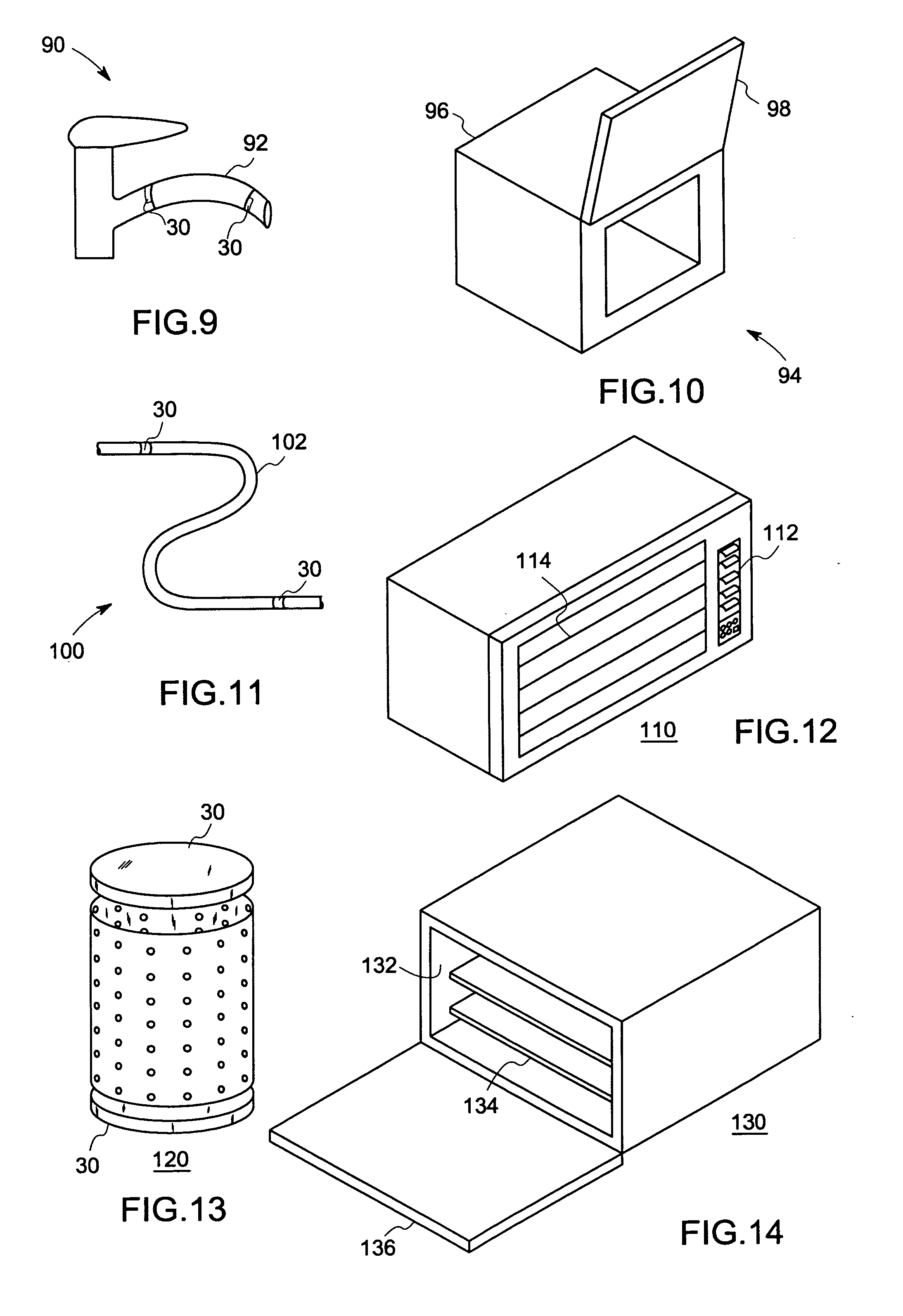
Disclosed herein are electrically conductive injection moldable compositions comprising an organic polymer, a nanosized conductive filler and / or carbon fibers having a diameter greater than 1000 nanometers, and / or graphite. The electrically conductive compositions can be advantageously resistively heated without undergoing substantial changes in shape. The ratio of either the nanosized conductive fillers and / or the carbon fibers to graphite is about 1:6 to about 1:80. The electrically conductive compositions are advantageously injection moldable and have melt viscosities of about 100 to about 600 Pascal-seconds (Pa-s).

In one embodiment, the conductive composition has a bulk volume electrical volume resistivity of less than or equal to about 10e8 ohm-cm and a surface resistivity greater than or equal to about 108 ohm / square. In another embodiment, the conductive composition has a surface resistivity less than or equal to about 108 ohm / square and a bulk volume resistivity less than...


PUM

PropertyMeasurementUnit
Fractionaaaaaaaaaa
Currentaaaaaaaaaa
Electrical conductoraaaaaaaaaa

Abstract

An apparatus with a self heating feature includes a conductive component of the apparatus having conductive composite. The conductive component is adapted to couple with a source of electricity, and the conductive component heats up on passage of electricity. According to another aspect, a domestic appliance that requires heating for its operation, includes at least one part comprising a conductive composite, which heats up on passage of electricity and the part is adapted to couple with a power supply. According to another aspect a method for providing heating in an apparatus includes heating at least one conductive component of the apparatus. The heating is done by passing an electric current through the conductive component, and the conductive component comprises a conductive composite.

Description

BACKGROUND The present invention relates generally to heating applications, and more specifically to methods and systems that provide self heating functionality to components of apparatuses or systems such as household appliances. Various household appliances require heating of certain parts or regions within the appliance. Such heating is required for purposes such as water evaporation, for example, from a defrost tray of a refrigerator; preventing condensation, for example, on refrigerator duct doors, refrigerator door dispensing assembly, air conditioning vents or louvers; defrosting, for example, dislodging ice from ice trays, preventing frost formation; drying, for example, cloth dryers, drying dishes in a dish washer; heating, for example, heating water in an in line water heating. Presently, such heating is done by providing a heating element, such as a resistive metal—shaped as a wire coil or a plate, at required parts or regions in an appliance. However, the use of heati...

Claims


Application Information

Patent Timeline
IPC IPC(8): C08K3/04C08K7/06F25D21/08H01B1/24H05B3/10
CPCB82Y30/00H05B2214/04F25D21/08C08K3/04C08L101/00H01B1/24
Inventor RAJARAJAN, SHANMUGAMDEVOS, RICHARDFLOYD, JENNIFERBANDYOPADHYAY, SUMANDAGHOSH, SOUMYADEBCHARATI, SANJAY GURBASAPPANAGESH, SURESHPARTHASARATHY, BALAJIJOSHI, ANAND GANESH
Owner GENERAL ELECTRIC CO
Why Eureka
Try Eureka