

Method of making sensor
a sensor and electrode technology, applied in the field of electrochemical sensors, can solve the problems of dimensional variation, micro-cracks, shrinkage, and dimensional variations, and achieve the effect of enhancing the performance and relieving pressur
- Summary
- Abstract
- Description
- Claims
- Application Information
AI Technical Summary
Benefits of technology
Problems solved by technology
Method used
Image

Examples
first embodiment
[0038] The First Embodiment
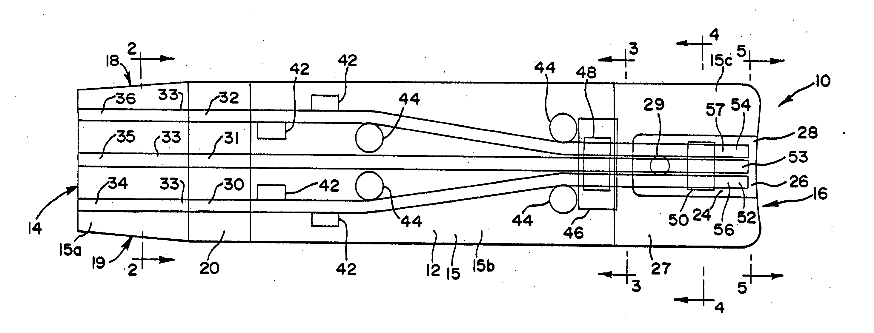
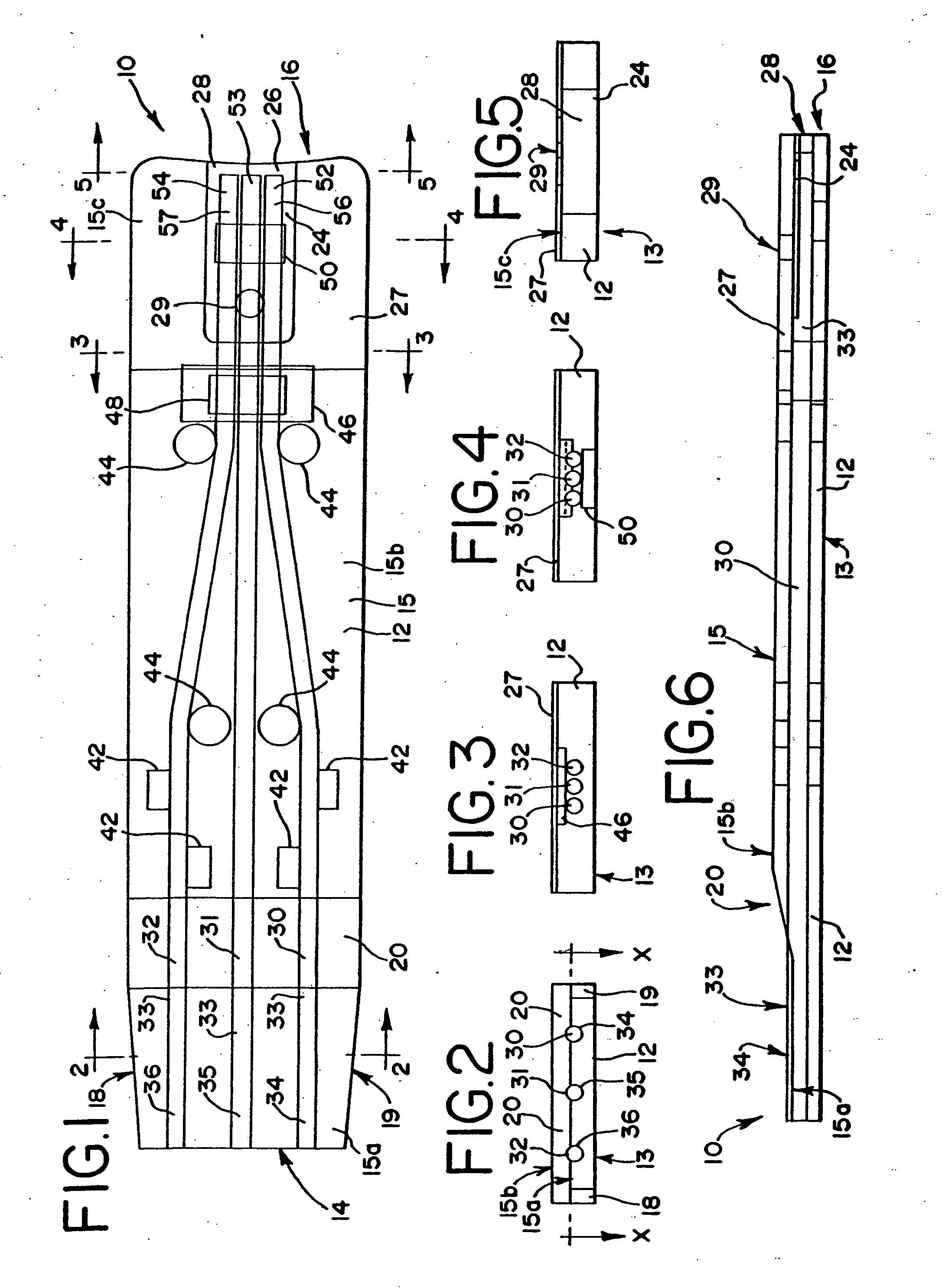
[0039] Referring to FIGS. 1-6, an electrochemical sensor in accordance with the present invention, first embodiment, is depicted. FIG. 1 shows the sensor 10 as though it were made out of clear plastic, permitting one to look inside it. As discussed herein, the internal components and hidden external components would not normally be visible looking down on the sensor 10. This rendition would be similar to a view taken along plane x-x in FIG. 2.
[0040] The sensor or test strip of the first embodiment 10 includes an injection molded plastic body 12, opaque or preferably translucent, having a meter attachment end or plug end 14 and a fluid sample receiving end 16. The body has a bottom surface 13, a top surface 15 and a tapered portion 20 connecting a first top surface 15a to a second top surface 15b, the first top surface being lower than the second top surface, and a third top surface 15c, also lower than the second top surface. The body 12 contains three sp...
second embodiment
[0042] While the cap 27 is shown as a separate piece, it can also be constructed as part of the body 12 and hingeably connected to the body such that it can be pivoted onto the third top surface 15c and attached [e.g., see The Second Embodiment]. In this manner, the entire sensor can be made at one time and as one molded, unitary piece.
[0043] A capillary opening 28 is formed in the terminal end 16 of the sensor 10 when the cap 27 is welded (or folded) to the body 12. This capillary opening leads to the reaction zone 24. Preferably, the sensor 10 is a capillary fill device, that is, the reaction zone 24 is small enough to draw a fluid sample into the zone when the capillary opening or inlet 28 is placed in contact with the fluid being tested, such as a drop of blood. Accordingly, if one wants to test his / her blood, s / he touches the terminal end 16 to the blood and the blood is drawn into the sensor 10 and reaction zone 24 through the capillary opening 28. This is much easier than pla...
third embodiment
[0083] The Third Embodiment
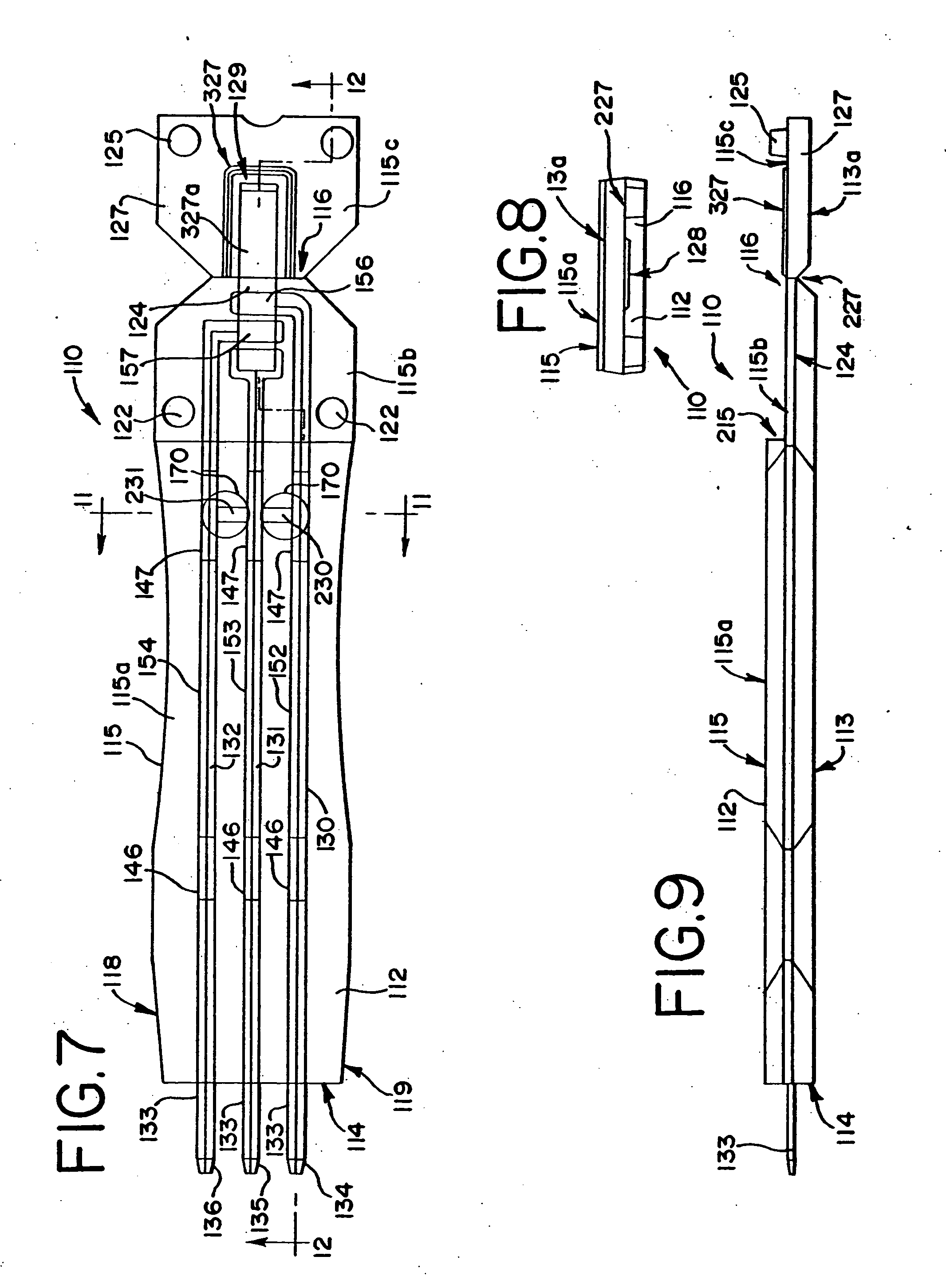
[0084] Shown in FIGS. 13-20 is a third embodiment of an electrochemical sensor in accordance with the present invention. These figures use the same reference numbers, but in the 300 series, to identify components that are similar to those in the previous embodiments. FIGS. 13 and 17, respectively, depict the sensor 310,310′ in its entirety, including its internal components not normally visible when looking down on the sensor 310,310′.
[0085] In the third embodiment sensor 310, 310′ is used in conjunction with a meter capable of measuring an electrochemical property of the fluid sample after the fluid sample is drawn into the reaction zone 324,324′. The sensor 310,310′ includes a molded plastic body 312,312′ having a meter attachment end or plug end 314,314′ and a fluid sample receiving end 316,316′. The plug end 314,314′ is insertable or connectable to a meter, as with the two prior embodiments. The body also has a bottom surface 313,313′ and a top surfac...
PUM
| Property | Measurement | Unit |
|---|---|---|
| electrically conductive | aaaaa | aaaaa |
| electrical properties | aaaaa | aaaaa |
| concentrations | aaaaa | aaaaa |
Abstract
Description
Claims
Application Information