Outer air seal assembly

a technology of outer air sealing and sealing parts, which is applied in the direction of engine sealing, leakage prevention, machines/engines, etc., can solve the problems of reducing engine efficiency, unwanted increase in engine cooling requirements, and radially directed leakage, so as to reduce radially directed leakage and increase the operational life of the seal, without reducing engine performance

Inactive Publication Date: 2005-03-31
SIEMENS ENERGY INC
View PDF14 Cites 19 Cited by
  • Summary
  • Abstract
  • Description
  • Claims
  • Application Information

AI Technical Summary

Benefits of technology

[0005] The present invention is an outer air seal assembly for use around rotating fluid guide components, such as turbine blades, within a gas turbine engine. The seal includes

Problems solved by technology

In situations where turbine section seals are used, a variety of difficulties may be encountered.
Turbine seals may a

Method used


Image

  • Outer air seal assembly
  • Outer air seal assembly
  • Outer air seal assembly

Examples


Embodiment Construction

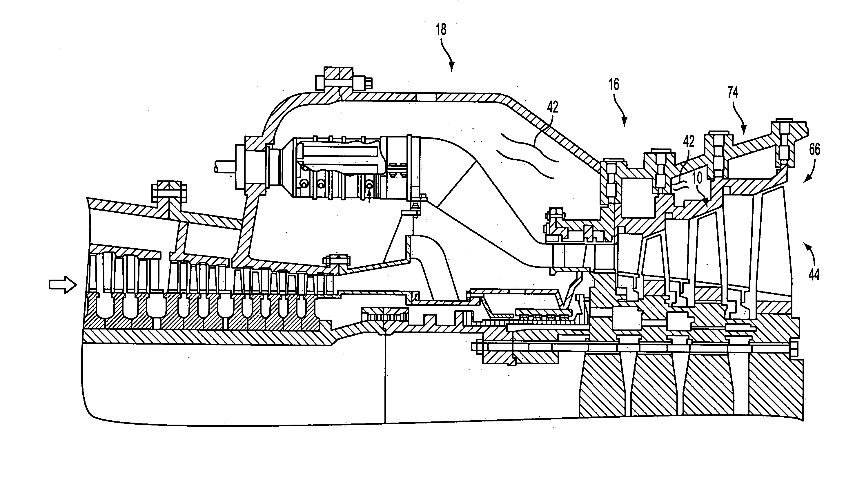
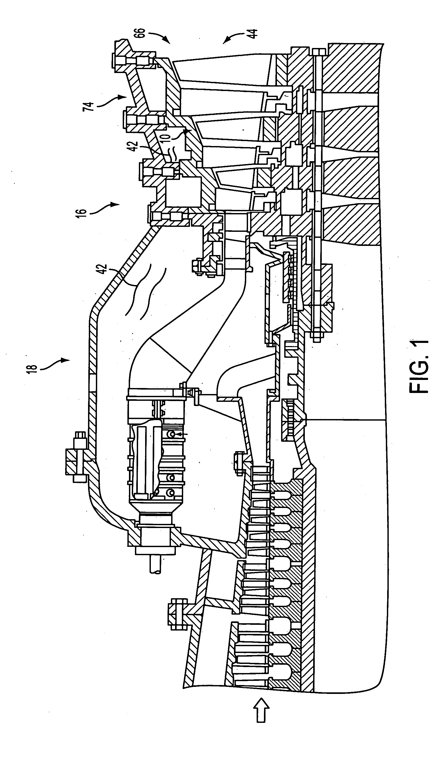
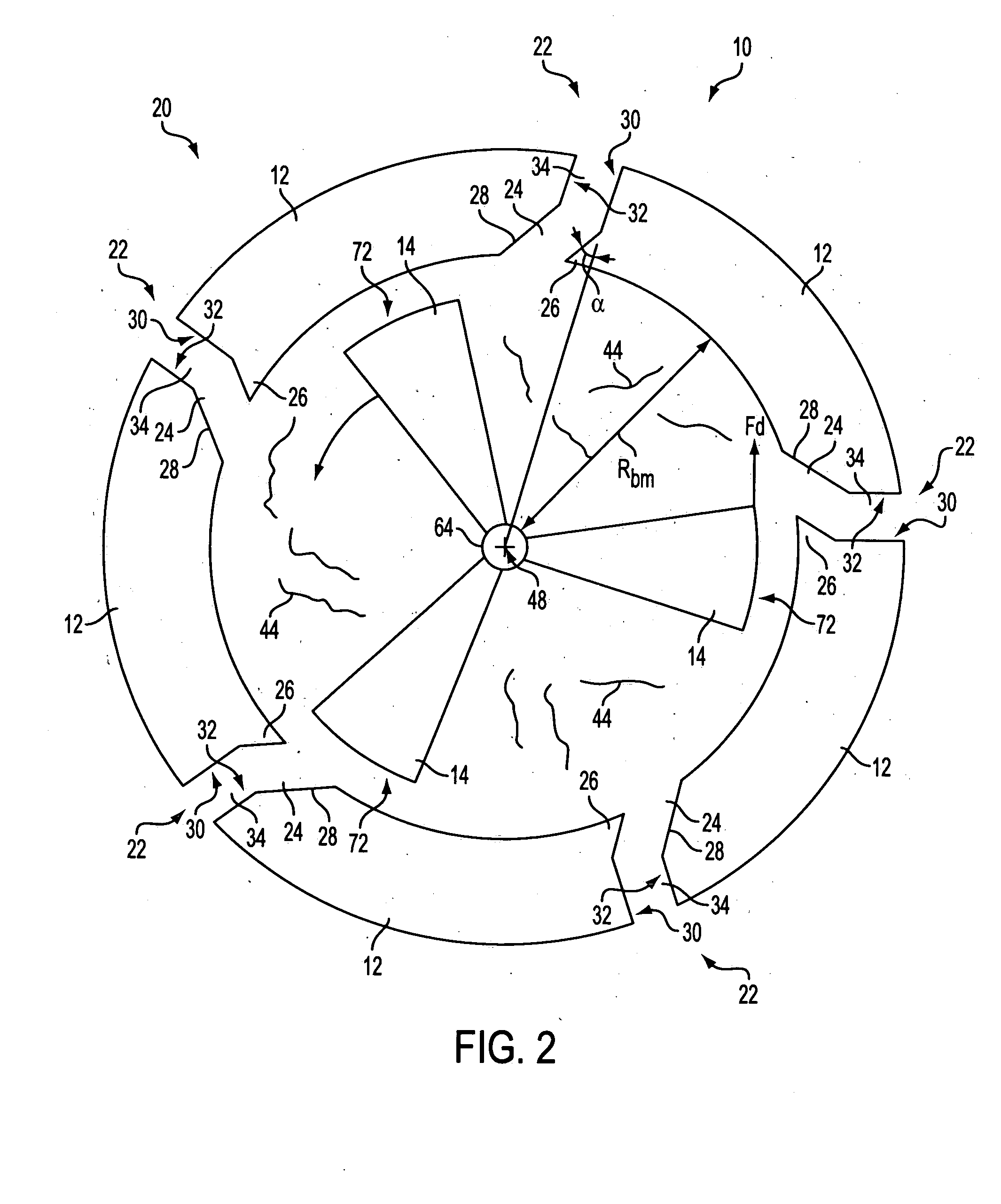
[0012] Reference is made to the Figures, generally, in which an outer air seal 10 according to the present invention is shown. By way of overview, the seal 10 includes a set 20 of boundary members 12 grouped in a ring-shaped arrangement to prevent leakage within the turbine section 16 of an associated gas turbine engine 18. Each boundary member 12 is separated from adjacent boundary members by interface gaps 22 formed therebetween. The interface gaps 22 allow contraction and expansion of individual boundary members 12, as well as relative motion between the boundary members, collectively, during operation. The interface gap 22 includes a radially-skewed portion 24 formed by angled portions 26,28 of cooperating, adjacent boundary member interface edges 30,32. The interface gap 22 may also include a radially-aligned portion 34, and one or more partition members 36 may extend into the interface gap 22 to form a serpentine-shaped pathway 38 within the gap. Cooling fluid conduits 40 disp...


PUM


Abstract

An outer air seal assembly for use around rotating fluid guide components, such as rotating blades within a turbine engine, is disclosed. The seal includes features that reduce radially-directed leakage while increasing operational life of the seal and providing additional turbine section cooling without reducing engine performance. The seal employs boundary members that cooperatively prevent leakage within the turbine section of an associated gas turbine engine. The boundary members are spaced apart by interface gaps having radially-skewed portions that protect blocking panels disposed within the gap and extends the life of seal. The interface gap may also include a radially-aligned portion, and partition members may extend into the gap to form a flow-slowing serpentine-shaped pathway within the gap. Conduits disposed within the boundary members allow cooling fluid to enter the interface gap, providing supplemental cooling benefits without reducing engine operating efficiency. Multiple sets of boundary members may be used in an axially-extending orientation, with interface gaps being disposed between boundary members of each set.

Description

FIELD OF THE INVENTION [0001] This invention relates generally to the field of internal to combustion engines and, more particularly, to an outer air seal having leakage-reducing and cooling-enhancing features. BACKGROUND OF THE INVENTION [0002] Combustion engines are machines that convert chemical energy stored in fuel into mechanical energy useful for generating electricity, producing thrust, or otherwise doing work. These engines typically include several cooperative sections that contribute in some way to the energy conversion process. In gas turbine engines, air discharged from a compressor section and fuel introduced from a fuel supply are mixed together and burned in a combustion section. The products of combustion (also referred to as the working gas or working fluid) are harnessed and directed through a turbine section, where they expand and turn a central rotor shaft. The rotor shaft may, in turn, be linked to devices such as an electric generator to produce electricity. [...

Claims


Application Information

Patent Timeline
IPC IPC(8): F01D11/00F16J15/44
CPCF16J15/442F01D11/005
Inventor LIANG, GEORGE
Owner SIEMENS ENERGY INC
Why Eureka
Try Eureka