
Lifting apparatus

a technology of lifting apparatus and lifting rod, which is applied in the direction of roofs, wing accessories, transportation and packaging, etc., can solve the problems of occupying interior space and adding weight to the vehicle, and achieve the effect of reducing the cost of supplemental energy needs and reducing vehicle cost and mass

Inactive Publication Date: 2005-03-31
GM GLOBAL TECH OPERATIONS LLC
View PDF17 Cites 17 Cited by
  • Summary
  • Abstract
  • Description
  • Claims
  • Application Information

AI Technical Summary

Benefits of technology

[0005] The actuator may be, but is not limited to, a hydraulic piston, a pneumatic piston or an electrically driven motor that applies a force to the extension member and causes the component to rise to a specific open position. Upon reversal of the actuator, the present invention retracts, causing the component to lower to a specific closed position. By providing a single actuator, the present invention allows the component to be lifted and lowered with power assistance.
[0006] The present invention assists in the raising and lowering of the component by utilizing an extension member that has extended travel capability with short travel inputs from the actuator. The short travel input of the extension member advantageously allows the extension member to be packaged easily within the automobile body while also providing the extended travel capability. Preferably, the extension member is a scissor jack extension member. Alternatively, the extension member is a telescoping hydraulic piston or similar extension member having extended travel capability with short travel inputs.
[0008] The present invention will function with either single or multi-pivoted hinges. The present invention advantageously reduces the cost of supplemental energy needs by utilizing a single actuator, provides a design solution for future closures that require dual-acting hinging, reduces the vehicle cost and mass by eliminating structural reinforcements in high load-bearing joints while also providing a power-assisted conventional lifting trunk or deck lid.

Problems solved by technology

The prior art retractable devices utilize a plurality of lifting apparatus for this function, disadvantageously occupying interior space and adding weight to the vehicle.

Method used


Image

  • Lifting apparatus
  • Lifting apparatus
  • Lifting apparatus

Examples


Embodiment Construction

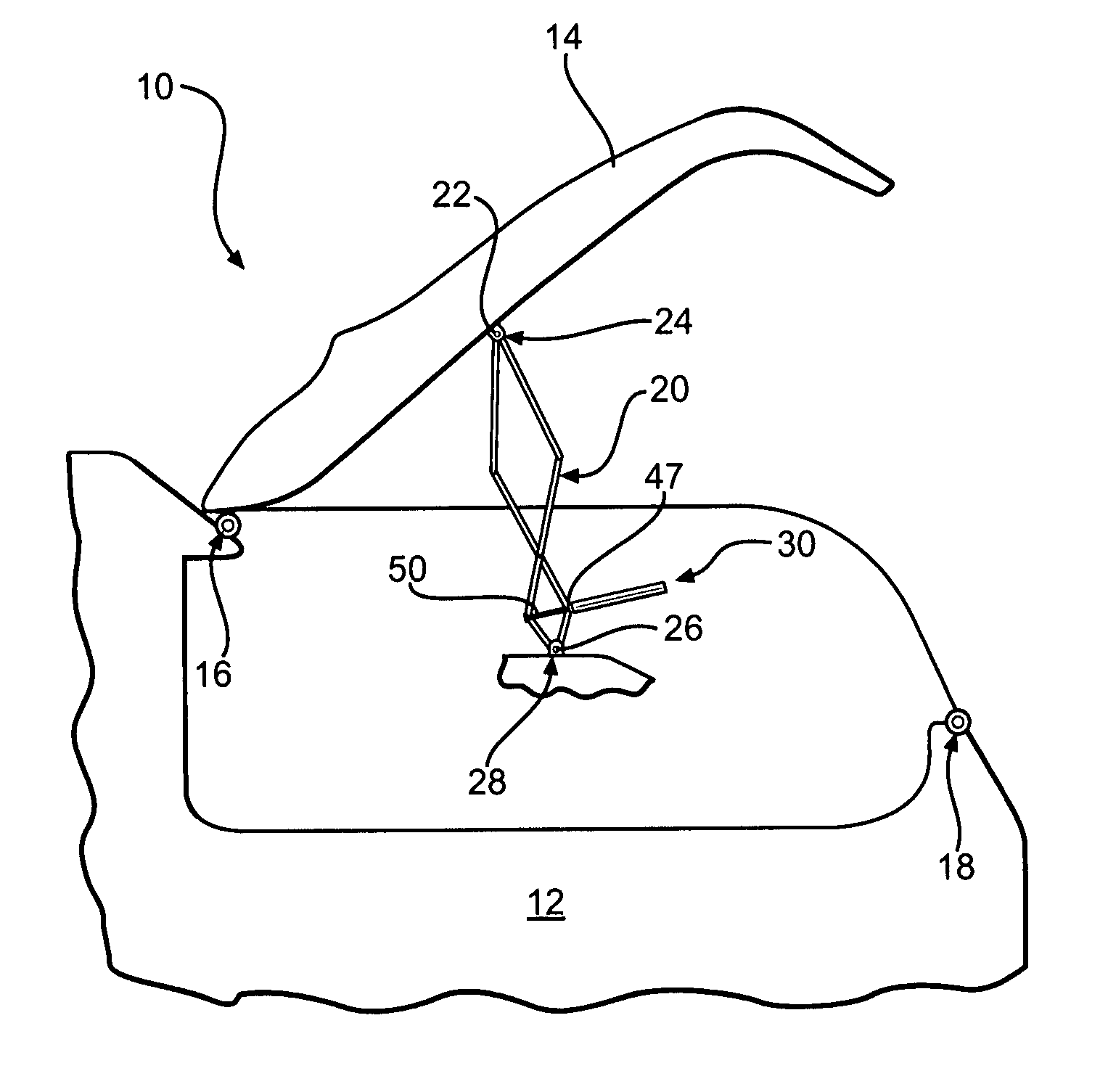
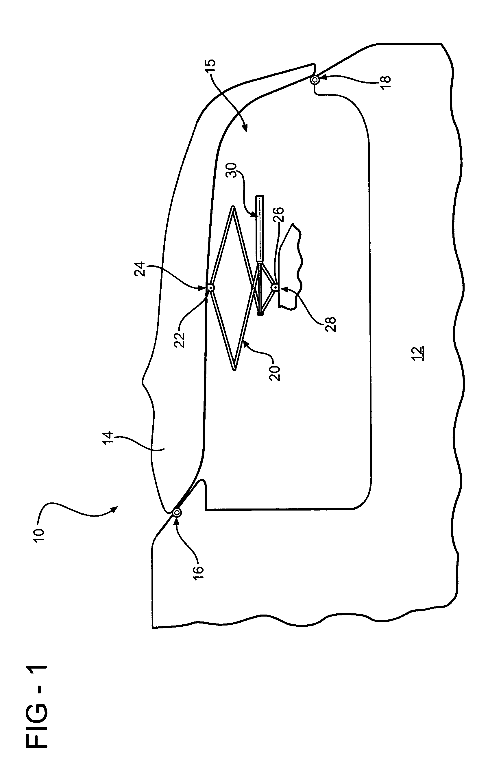
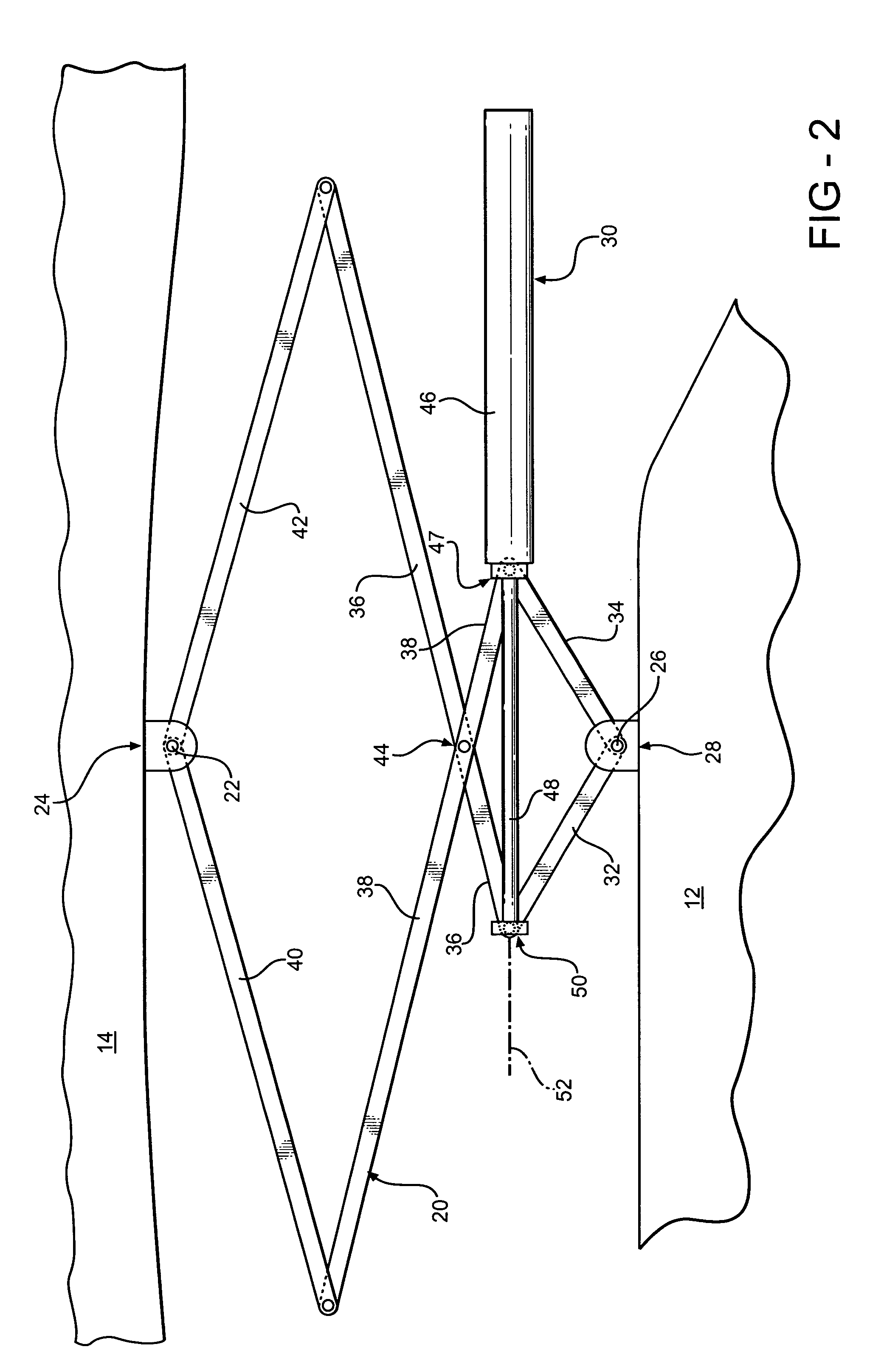
[0015] Referring now to FIG. 1, a lifting apparatus in accordance with the present invention is indicated generally at 10. The lifting apparatus 10 is adapted to be attached to an automobile body 12 or any other type of body having a moveable closure. Only a rear portion of the vehicle body 12 is shown in side elevation with the near side removed to expose the interior thereof. The apparatus 10 is representative of two such devices which would be mounted at opposite sides of the vehicle body. The lifting apparatus 10 is attached to a moveable body component 14, such as a trunk lid, a deck lid or the like. The component 14 is attached to the automobile body 12 at a first latch or attachment point 16 and a second latch or attachment point 18 on opposing ends thereof. The first attachment point 16 and the second attachment point 18 are preferably hinged and releasable latches, discussed in more detail below. The component 14 releasably encloses a compartment 15 formed in the automobile...


PUM


Abstract

A lifting apparatus for lifting and lowering a component of an automobile body that is hingedly and releasably attached to the automobile body at first and second attachment points. The lifting apparatus includes an extension member having first and second ends that is operable to move from a normally retracted position to an extended position. The first end of the extension member is pivotally attached to the component at a third attachment point and the second end of the extension member is pivotally attached to the automobile body. An actuator is operable to extend and retract the extension member. When a one of the first and second attachment points is released, the extension member moves from the retracted position to the extended position and moves the component to an open position about the other of the first and second attachment points.

Description

BACKGROUND OF THE INVENTION [0001] The present invention relates in general to lift mechanisms and, in particular, to a lifting apparatus for lifting a moveable body component away from an automobile body. [0002] Automotive lift mechanisms are well known and are utilized for moving a body component, for example, a vehicle swinging panel such as vehicle rear doors and lift gates that are hinged to a vehicle body. The components to be lifted are typically attached at and pivot about a single axis when lifted to allow access to the trunk or vehicle interior. Recent innovations in automotive accessories include retractable devices, such as a retractable vehicle hard top, that are designed to be stowed adjacent the trunk lid of vehicles. These retractable devices are preferred to be stowed utilizing existing vehicle body components, such as the vehicle trunk lid. In order to stow the retractable device and continue to function as a trunk lid, however, the trunk lid must be hingedly and r...

Claims


Application Information

Patent Timeline
Patent Type & Authority Applications(United States)
IPC IPC(8): B60J7/20E05D15/50E05F15/04E05F15/12
CPCB60J7/205E05D15/50E05Y2201/604E05Y2201/694E05F15/63E05Y2900/536E05Y2900/548E05Y2900/50E05Y2900/508
Inventor KRAJENKE, GARY WALTER
Owner GM GLOBAL TECH OPERATIONS LLC
Learn More