

Magnetic resonance imaging apparatus and central frequency estimating method
- Summary
- Abstract
- Description
- Claims
- Application Information
AI Technical Summary
Benefits of technology
Problems solved by technology
Method used
Image

Examples
first embodiment
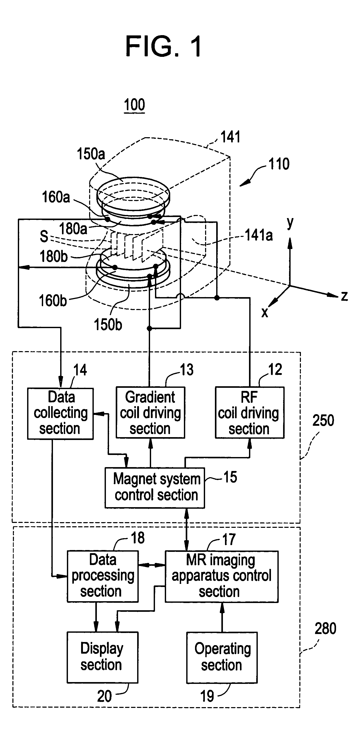
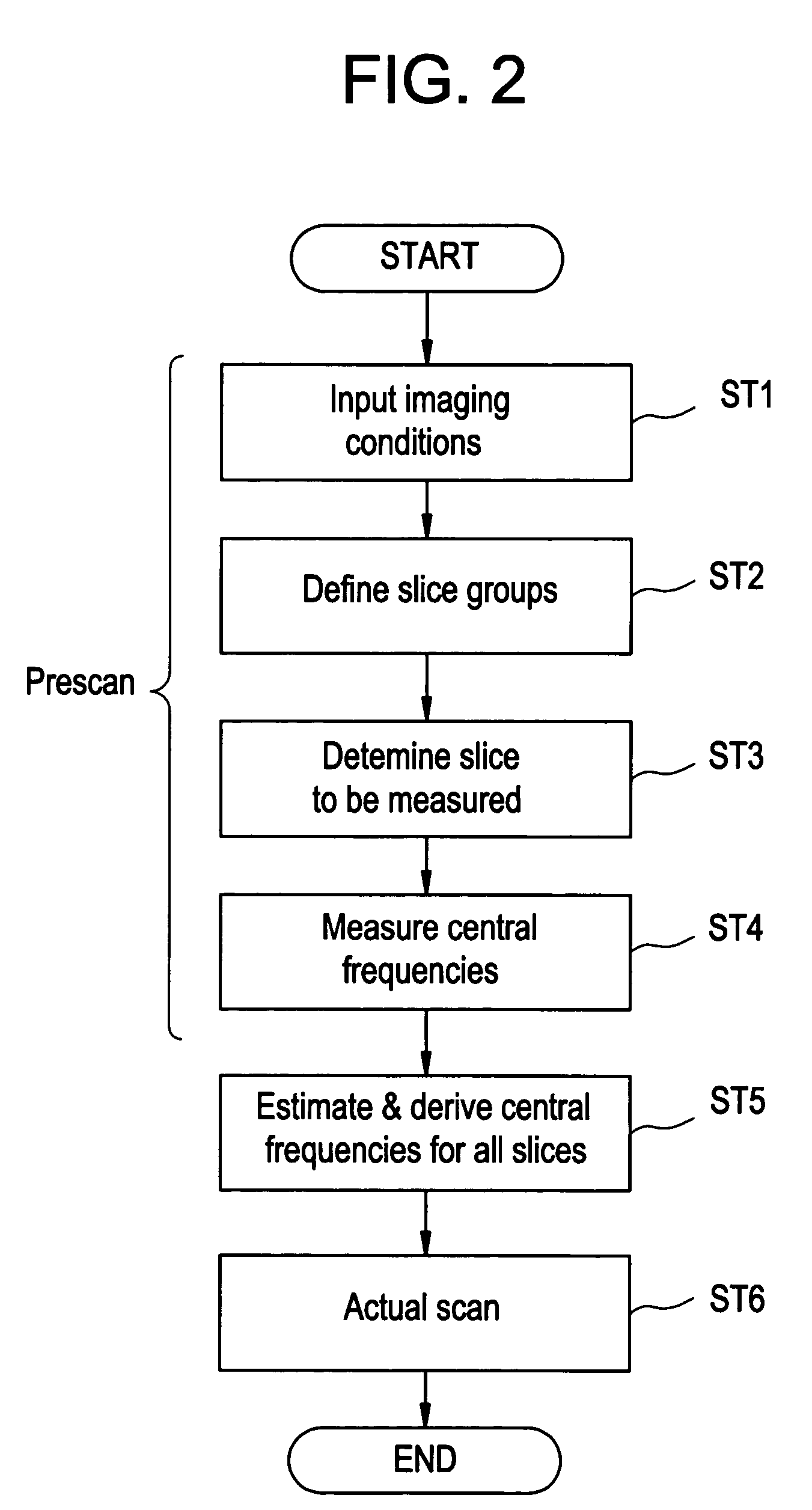
[0030]FIG. 1 is a schematic block diagram that generally shows the configuration of an MR (magnetic resonance) imaging apparatus in accordance with the first embodiment of the present invention.
[0031] An MR imaging apparatus 100 shown in FIG. 1 comprises a main body section 110 and a console section 280. In FIG. 1, the main body section 110 is illustrated in a schematic perspective phantom view of its main portion.
[0032] The main body section 110 comprises a magnet system and a driving section 250.
[0033] The magnet system includes a pair of static magnetic field generating magnet sections 150a and 150b, gradient coil sections 160a and 160b, and RF (radio frequency) coil sections 180a and 180b, each member being disposed to face its counterpart in a housing 141 of the main body section 110.
[0034] These sections are disposed with each member facing its counterpart and are arranged in order of, for example, the RF coil sections 180a and 180b, gradient coil sections 160a and 160b, a...
second embodiment
[0122] The central frequencies of slices other than a slice to be measured may be estimated by fitting, rather than by assigning the measured central frequency of the slice to be measured to them as is. Such an example will be described hereinbelow as a second embodiment.
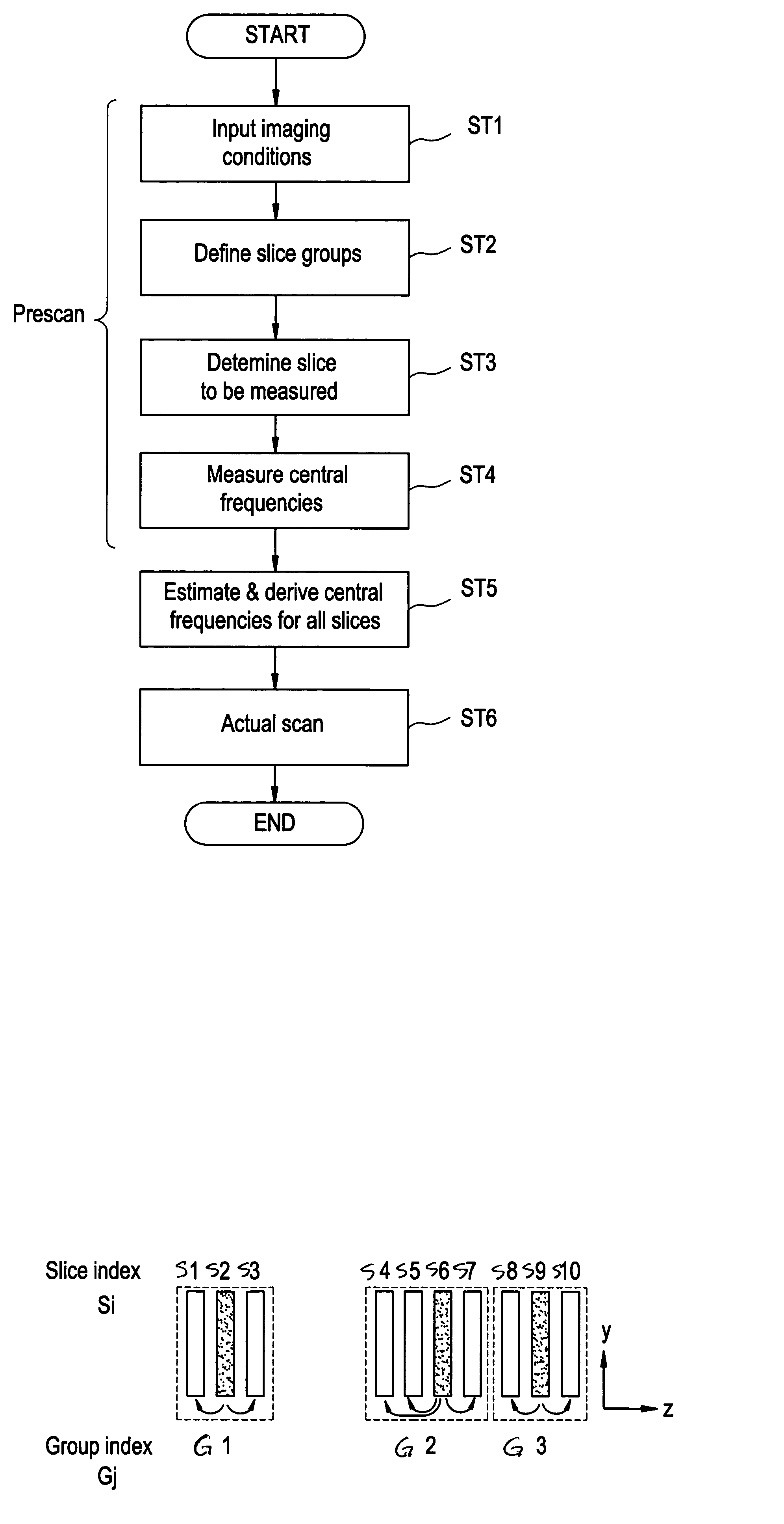
[0123]FIG. 5 is a diagram showing an exemplary pattern of defining slice groups in the second embodiment. FIG. 5 is illustrated with a plurality of slices Si arranged in parallel to one another in the z-direction, as viewed in the x-direction with magnification, as in FIG. 4.
[0124] The MR apparatus 100 for use in the second embodiment is generally same as that in the first embodiment. Therefore, detailed description thereof is omitted. Moreover, since the procedure of estimating central frequencies is also generally the same as that shown in FIG. 2, detailed description thereof is omitted.
[0125] In the second embodiment, it is assumed that the magnet system 15 has executed the processing of grouping the slices Si...
third embodiment
[0137] If the variation of the magnetic field is smooth, central frequencies can be somewhat accurately estimated by the second embodiment; however, the variation of the magnetic field is not always smooth. In the third embodiment, a mode that can accommodate an irregular variation of the magnetic field is addressed.
[0138]FIG. 6 is a diagram showing an exemplary pattern of defining slice groups in the third embodiment. FIG. 6 is illustrated with a plurality of slices Si arranged in parallel to one another in the z-direction, as viewed in the x-direction with magnification, as in FIG. 4. FIG. 6 exemplifies a case in which the number of slices S whose central frequencies can be measured is seven, and a unitary imaged region Ar of fifteen slices S is grouped with the largest number of slices S contained in one group being three.
[0139] Since the configuration of the MR apparatus 100 and the procedure of estimating central frequencies for use in the third embodiment are generally same ...
PUM
 Abstract
Description
Claims
Application Information