
Tube pump

Inactive Publication Date: 2005-03-31
JAPAN SERVO CO LTD
View PDF6 Cites 30 Cited by
  • Summary
  • Abstract
  • Description
  • Claims
  • Application Information

AI Technical Summary

Benefits of technology

[0010] A first object of the present invention is to provide a tube pump that can increase structural strength of a casing so that it can be made from plastic with easy attachment and removal of an elastic tube.
[0011] A second object of the present invention is to provide a tube pump that does not require a mechanism for locking a casing at an operating position on the precondition that a roller changes its position in response to opening / closing of a cover between the operating position where the roller deforms the elastic tube and an exchange position where the roller comes apart from the elastic tube.
[0012] A third object of the present invention is to provide a tube pump that can automatically operate clamp arms arranged at entrance and exit positions of the pump.

Problems solved by technology

Since the tube pump sends liquid by deforming the elastic tube, the tube tends to deteriorate, which requires frequent exchange of the tube.
However, since the elastic tube is pinched between one roller and the internal surface of the tube pump, it takes much expense in time and effort to exchange the tube even if the rotor portion stops.
However, since the tube pump disclosed in the above publication divides the semicircular internal surface to which large pressure is applied by the rotation of the rotor portion in operation into two portions, it is difficult to keep structural strength.
Therefore, the movable and fixed casings are formed from metal, which increases the cost of the tube pump in comparison with that with plastic casings.
Although the publication describes that the casings may be made from plastic, if the casings having the same structure are made from plastic, there is a high probability that the casings break due to lack of strength in reality.
However, since the casing to which large pressure is applied is divided as described above, a solenoid to lock the movable casing at the position connecting to the fixed casing and a sensor that detects the opening and closing of the cover to control the solenoid are required, which complicates the construction of the tube pump.
However, since the clamp arms must be operated manually, the operation of the clamp arms for exchanging the tube is complicated.

Method used


Image

  • Tube pump
  • Tube pump
  • Tube pump

Examples


Embodiment Construction

[0034] Hereinafter, a tube pump of an embodiment according to the present invention will be described with reference to the drawings. Initially, an example of the use of the tube pump of the embodiment will be described according to FIG. 9.

[0035]FIG. 9 shows the entire construction of artificial dialysis equipment 2 that employs the tube pump 1 of the embodiment as a blood pump. The artificial dialysis equipment 2 is provided with the tube pump 1, a dialyzer 3, first and second chambers 4 and 5. The equipment 2 is incorporated in an extracorporeal circulation path of a patient P. In addition, the reference F in FIG. 9 indicates a cover sheet put on the body of the patient P.

[0036] Blood collected from the arm of the patient P is drawn by the tube pump 1 through the tube and is pressurized to send to the first chamber 4. The blood that is temporally accumulated in the first chamber 4 is sent to the dialyzer 3. The dialyzer 3 dialyzes and filters the blood with using a dialyzate sol...


PUM


Abstract

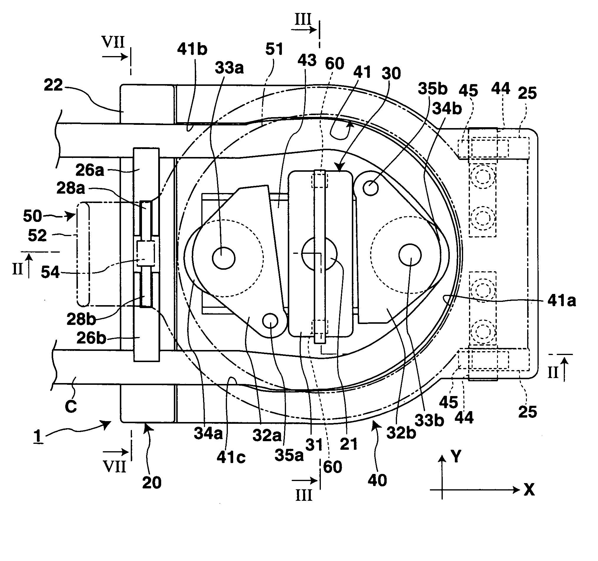
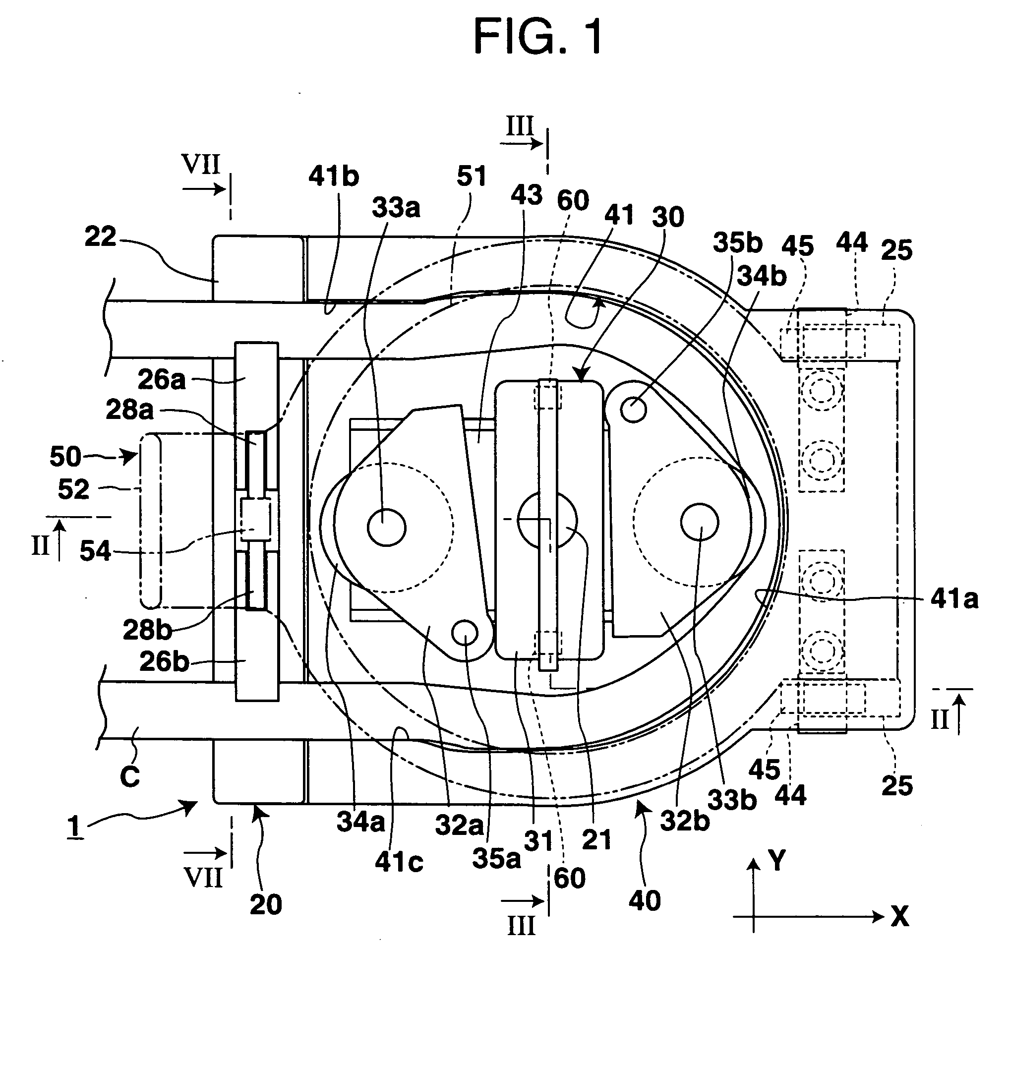
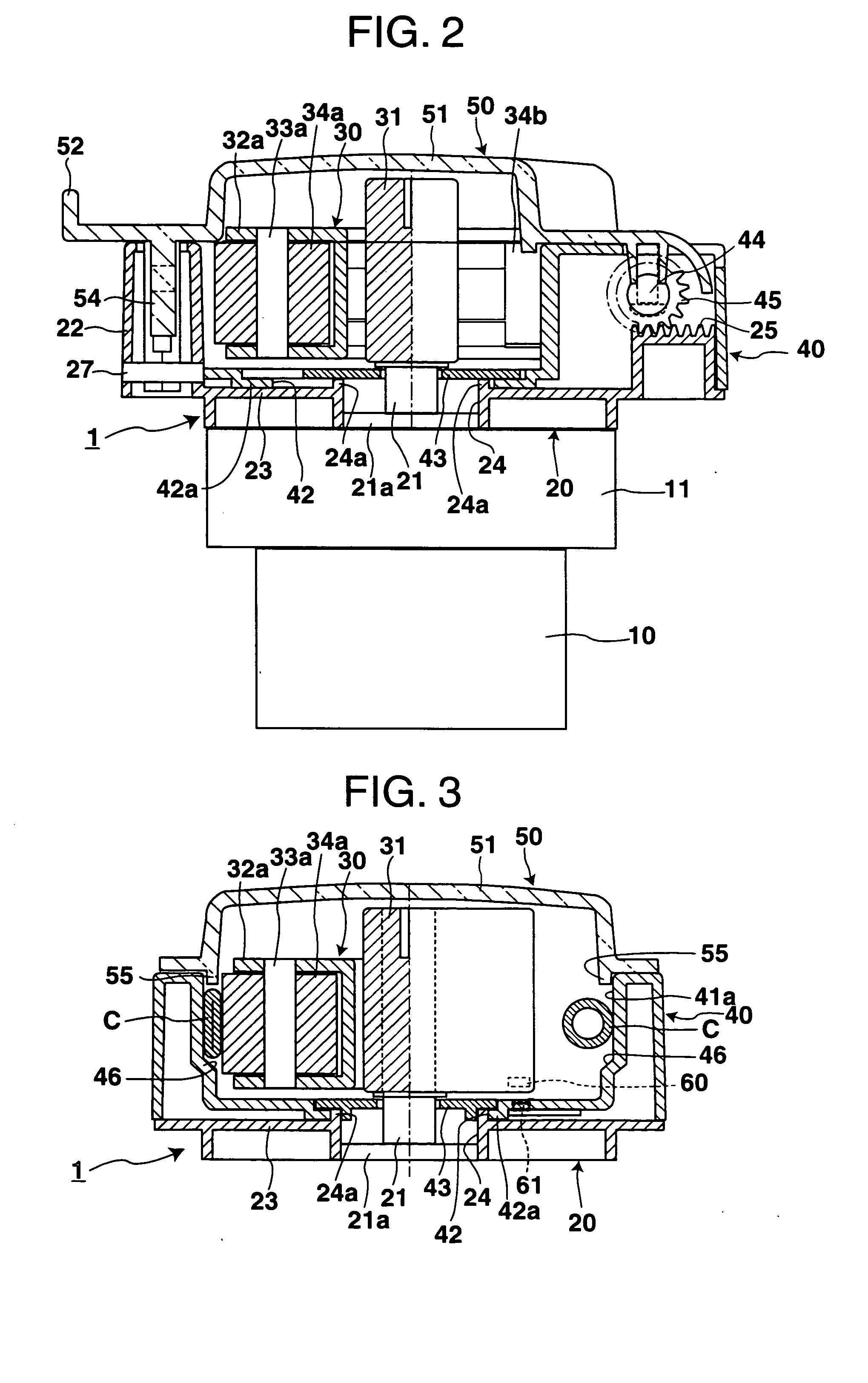
The tube pump includes a base that holds a drive shaft; a rotor portion that rotates with the driving shaft, the rotor portion having a pair of rollers; a casing having a U-shaped internal surface along which an elastic tube is arranged, the casing being mounted on the base so that the casing can slide with respect to the base in a direction parallel to the linear portions; a cover that is rotatably mounted on the casing; a moving mechanism including a rack that is formed on the base and a pinion that is fixed to the rotation shaft of the cover. The moving mechanism moves the casing to the operating position where the roller deforms the elastic tube when the cover closes, and the moving mechanism moves the casing to the exchange position where the roller comes apart from the elastic tube when the cover opens.

Description

BACKGROUND OF THE INVENTION [0001] 1. Field of the Invention [0002] The present invention relates to a tube pump that deforms an elastic tube by rotating rollers to send out liquid in the elastic tube. Especially the present invention relates to a tube pump mounted on artificial dialysis equipment etc. that enables easy attachment and removal of the elastic tube. [0003] 2. Prior Art [0004] This kind of tube pump is disclosed in Japanese unexamined patent publication No. Hei 6-218042, for example. The tube pump disclosed in the publication is provided with a casing body having a semicircular internal surface, a drive shaft located at the center of the semi-circle and a rotor portion that rotates with the drive shaft. The rotor portion has a pair of rollers whose rotation axes are decentered from the drive shaft. For operation, arrange an elastic tube along the internal surface of the casing body and rotate the rotor portion to deform the elastic tube with compression between the inte...

Claims


Application Information

Patent Timeline
IPC IPC(8): F04C5/00A61M1/10F04B43/12
CPCF04B43/1284A61M1/1037A61M60/113A61M60/279A61M60/37
Inventor SHIBASAKI, MASANORI
Owner JAPAN SERVO CO LTD
Learn More