Photolithographic method for manufacturing a mold for a light guide plate

a technology of light guide plate and manufacturing method, which is applied in the direction of photomechanical equipment, instruments, originals for photomechanical treatment, etc., can solve the problem that the manufacturing method requires relatively few and simple steps, and achieve the effect of high precision

Inactive Publication Date: 2005-03-31
HON HAI PRECISION IND CO LTD
View PDF4 Cites 1 Cited by
  • Summary
  • Abstract
  • Description
  • Claims
  • Application Information

AI Technical Summary

Benefits of technology

[0010] An object of the present invention is to provide a manufacturing method f

Problems solved by technology

In addition, the manufacturing method r

Method used


Image

  • Photolithographic method for manufacturing a mold for a light guide plate
  • Photolithographic method for manufacturing a mold for a light guide plate
  • Photolithographic method for manufacturing a mold for a light guide plate

Examples


Embodiment Construction

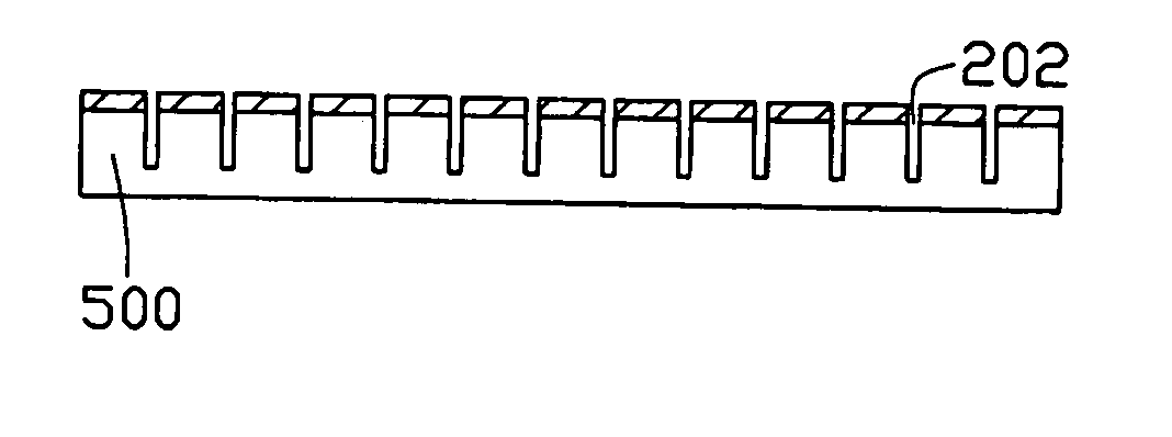
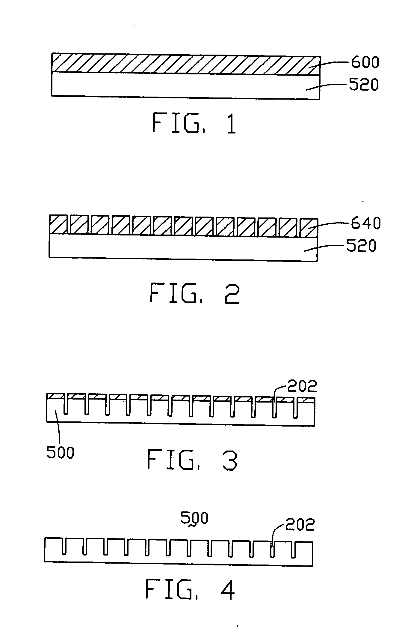
[0018] FIGS. 1 to 4 are views illustrating stages in a method for manufacturing a mold for a light guide plate according to the present invention. The mold enables the light guide plate to have a plurality of precise diffusion dots integrally formed thereon. The manufacturing method includes the following steps: [0019] (1) forming a photo-resist film 600 on a substrate 520, as shown in FIG. 1; [0020] (2) disposing a mask (not shown) having a predetermined pattern over the substrate 520, and exposing the photo-resist film 600 to light through the mask; [0021] (3) developing the photo-resist film 600 to form a photo-resist pattern 640 on the substrate 520, as shown in FIG. 2; [0022] (4) dry-etching the substrate 520 and the photo-resist pattern 640 simultaneously to form a mold preform having a plurality of generally rectangular grooves 202, as shown in FIG. 3; and [0023] (5) stripping the residual photo-resist pattern 640 from the mold preform to obtain the mold 500 for a light guide...


PUM


Abstract

A method for manufacturing a mold for a light guide plate includes the steps of: providing a substrate (520); forming a photo-resist film (600) on the substrate; disposing a mask having a predetermined pattern over the substrate, illuminating the photo-resist film through the mask by illuminating rays; developing the photo-resist film to form a photo-resist pattern (640) on the substrate; dry-etching the substrate and the photo-resist pattern simultaneously to form a mold preform; and stripping the residual photo-resist pattern from the patterned substrate to attain the mold (500). The method is highly precise and relatively simple.

Description

CROSS-REFERENCE TO RELATED APPLICATION [0001] This application is related to the application by Ga-Lane Chen, Kun-Jung Tsai and Tai-Cherng Yu, entitled METHOD FOR MANUFACTURING LIGHT GUIDE PLATE STAMPER filed in an earlier time, and assigned to the same assignee as the present application. BACKGROUND OF THE INVENTION [0002] 1. Field of the Invention [0003] The present invention relates to method for manufacturing molds for light guide plates, and particularly to a method for manufacturing a mold for a light guide plate using photolithography technology. [0004] 2. Prior Art [0005] In a liquid crystal display device, a backlight module is commonly used to provide a planar light source for illuminating the liquid crystal display. In general, the backlight module includes a light source and a light guide plate, the light source being located adjacent to one side of the light guide plate. The light guide plate transforms light beams emitted from the light source into planar light beams, ...

Claims


Application Information

Patent Timeline
IPC IPC(8): F21V8/00G03F7/00
CPCG03F7/0017G02B6/0065
Inventor LEU, CHARLESYU, TAI-CHERNGCHEN, GA-LANE
Owner HON HAI PRECISION IND CO LTD
Why Eureka
Try Eureka