
Ultrasonic surgical system, and abnormality detection method and abnormality detection program for ultrasonic surgical system

Inactive Publication Date: 2005-03-31
OLYMPUS CORP
View PDF11 Cites 307 Cited by
  • Summary
  • Abstract
  • Description
  • Claims
  • Application Information

AI Technical Summary

Benefits of technology

[0006] It is an object of the present invention to at l

Problems solved by technology

If an overload is imposed on a vibration system in the ultrasonic surgical system due to one of various abnormalities such as a damage of the probe, adhesion of a blood or the like, and a malfunction and the like of the handpiece, the ultrasonic vibrator of this ultrasonic surgical system is difficult to drive at the resonance frequency or the near-resonance frequency.
This results in deterioration of a function of the ultrasonic surgical system to ensure performing the medical treatment.

Method used


Image

  • Ultrasonic surgical system, and abnormality detection method and abnormality detection program for ultrasonic surgical system
  • Ultrasonic surgical system, and abnormality detection method and abnormality detection program for ultrasonic surgical system
  • Ultrasonic surgical system, and abnormality detection method and abnormality detection program for ultrasonic surgical system

Examples


first embodiment

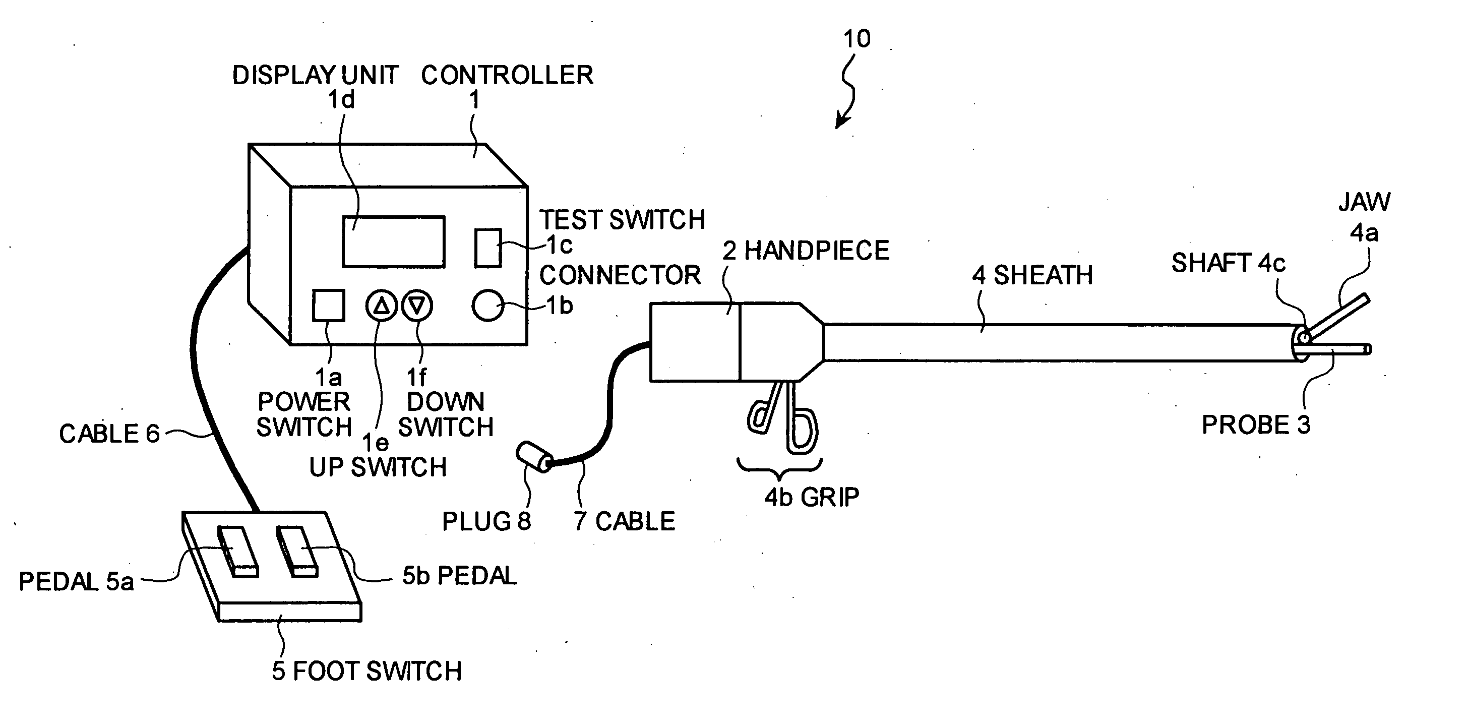
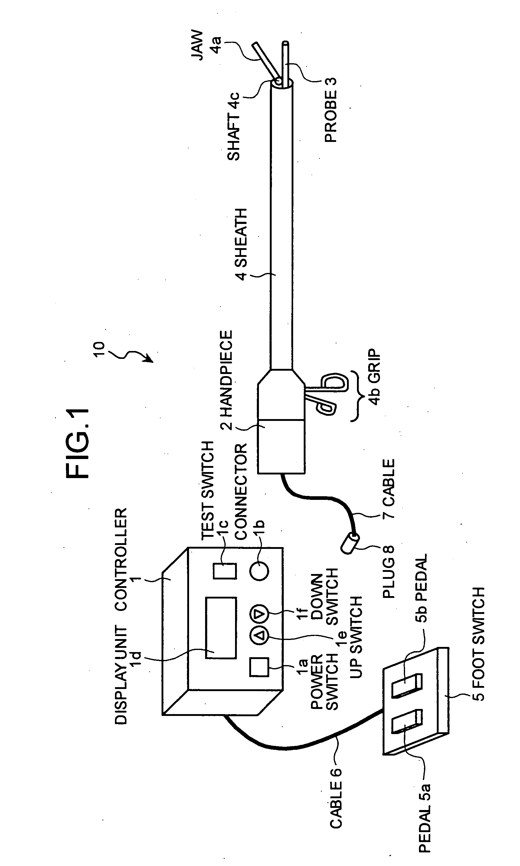
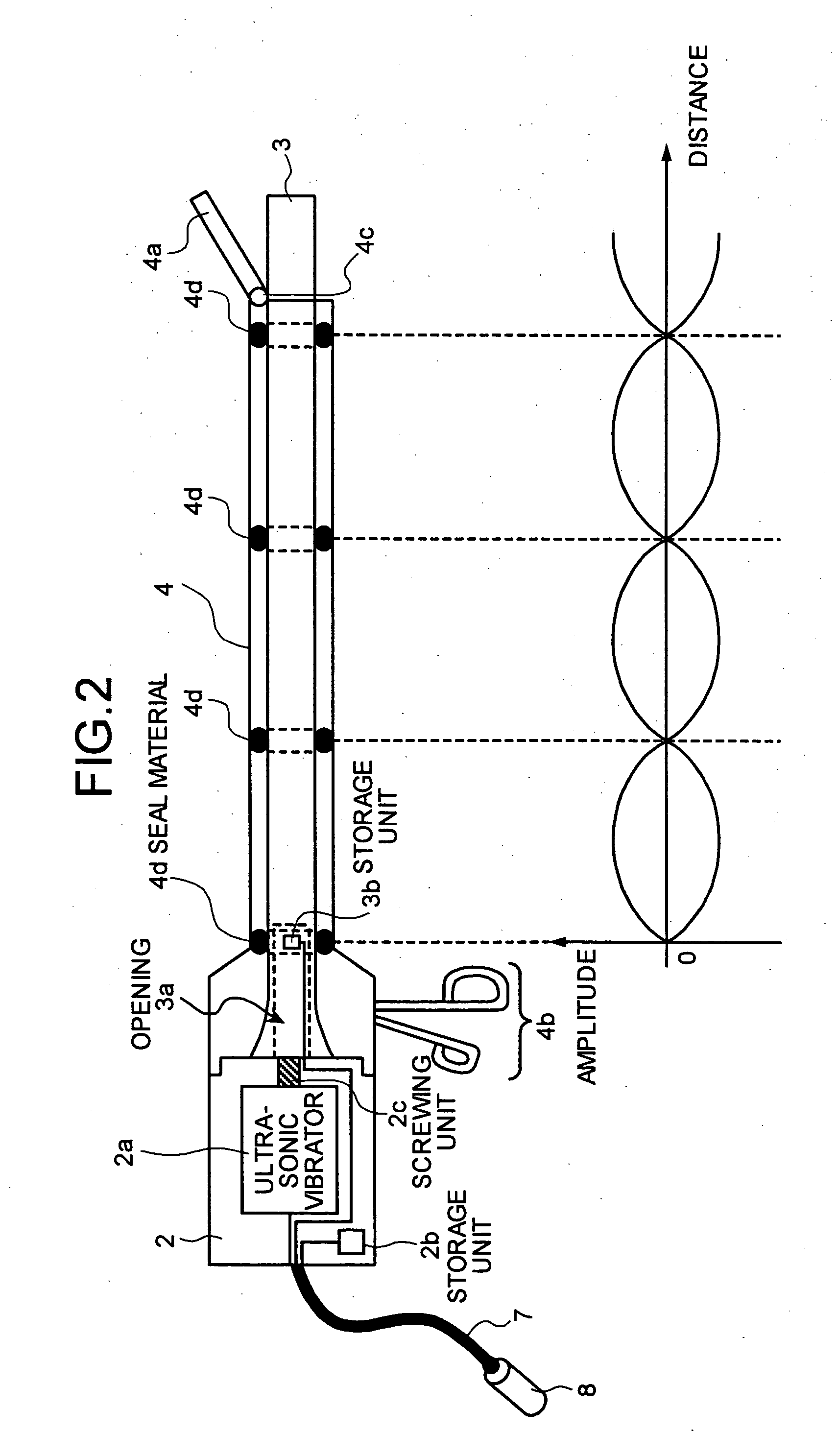
[0026]FIG. 1 is a typical view of the schematic configuration of the ultrasonic surgical system according to the present invention. In FIG. 1, the ultrasonic surgical system 10 includes a controller main unit (hereinafter, “controller”) 1, a handpiece 2, a probe 3, a sheath 4, and a foot switch 5. The controller 1 includes a power switch 1a, a connector 1b, a test switch 1c, a display unit 1d, an up switch 1e, and a down switch 1f. The handpiece 2 includes an ultrasonic vibrator (not shown) therein. The probe 3 is screwed with this ultrasonic vibrator. The probe 3 is inserted into the sheath 4, and the sheath 4 is detachably connected to the handpiece 2. If so, the sheath 4 covers the probe 3 for carrying out a medical treatment to a treatment target so as to expose a tip end of the probe 3 from a tip end of the sheath 4. The foot switch 5 includes pedals 5a and 5b, and is electrically connected to the controller 1 through a cable 6. The handpiece 2 includes a cable 7 having a plug ...

second embodiment

[0115] the short-circuit detection unit 22 detects the continuity resistance of the closed circuit formed by the probe 3, the jaw 4a, and the short-circuit detection unit 22. In addition, the short-circuit detection unit 22 detects the short-circuit between the probe 3 and the jaw 4a based on the result of the comparison between the continuity resistance and the continuity resistance limit serving as the continuity determination criterion. However, the present invention is not limited to this embodiment. The short-circuit detection unit 22 may detect the current of the electric signal conducted to the closed circuit formed by the probe 3, the jaw 4a, and the short-circuit detection unit 22, and may detect the short-circuit between the probe 3 and the jaw 4a based on the result of the comparison between the current and the current limit serving as the continuity determination criterion.

[0116] According to the second embodiment, the short-circuit detection unit 22 is provided in the ...


PUM


Abstract

An ultrasonic surgical system includes a handpiece having an ultrasonic vibrator; and a probe connected to the ultrasonic vibrator. The handpiece includes a first storage unit that stores first determination criterion information being a criterion of whether an abnormality occurs in the ultrasonic surgical system. The probe includes a second storage unit that stores second determination criterion information as a criterion of whether an abnormality occurs in the ultrasonic surgical system. The ultrasonic surgical system also includes a control unit that stops driving the ultrasonic vibrator based on the first and second determination criterion information.

Description

BACKGROUND OF THE INVENTION [0001] 1) Field of the Invention [0002] The present invention relates to an ultrasonic surgical system which performs a surgical, medical treatment such as coagulation and incision of a biological tissue, lithotrity, and aspiration by applying an ultrasonic vibration, and an abnormality detection method and an abnormality detection program for the ultrasonic surgical system. [0003] 2) Description of the Related Art [0004] There has been conventionally developed an ultrasonic surgical system which includes a handpiece having an ultrasonic vibrator incorporated therein and a probe connected to the ultrasonic vibrator, which contacts a probe, to which an ultrasonic vibration is transmitted, with a biological tissue or the like, and which conducts a surgical, medical treatment such as incision, excision, or aspiration to the biological tissue. The ultrasonic vibration output from the ultrasonic vibrator of this ultrasonic surgical system is realized by contro...

Claims


Application Information

Patent Timeline
IPC IPC(8): A61B17/28A61B17/00A61B17/32A61B18/00A61B19/00
CPCA61B17/320092A61B2017/0003A61B2019/448A61B2017/00132A61B2017/00973A61B2017/00115A61B2018/00988A61B90/98A61B2017/320093A61B2017/320095
Inventor TAKAHASHI, HIROYUKI
Owner OLYMPUS CORP
Learn More