Methods and systems for predicting electromagnetic scattering

a technology of electromagnetic scattering and electromagnetic waves, applied in the field of automatic electromagnetic scattering prediction, can solve the problems of difficult to formulate the appropriate ie for geometrically complex inhomogeneous structures, cost and time, and inability to accurately predict the effect of electromagnetic scattering, so as to reduce computational effort and reduce the cost and time required, the effect of improving the efficiency of the prediction process

Active Publication Date: 2005-03-31
THE BOEING CO
View PDF2 Cites 26 Cited by
  • Summary
  • Abstract
  • Description
  • Claims
  • Application Information

AI Technical Summary

Benefits of technology

The present invention is directed to methods and systems for predicting electromagnetic scattering from a target. Embodiments of methods and systems in accordance with the present invention may substantially reduce the computational effort required to predict electromagnetic scattering, thereby decreasing the cost and time required to perform such calculations, and improving the efficiency of the prediction process, in comparison with prior art methods and systems.

Problems solved by technology

However, even with a significant reduction in the number of unknowns, the computational cost of generating the full system matrix and the difficulties in solving the linear equations often makes this approach costly and slow.
It is also difficult to formulate the appropriate IE for geometrically complex inhomogeneous structures, possibly requiring a nontrivial derivation of a geometry-dependent Green's function.
Setting these parameters is always a trade off between simulation accuracy and simulation speed.
The larger the number of cells, the more accurate the solution, but slower and more expensive, in terms of computer resources, the solution becomes.

Method used


Image

  • Methods and systems for predicting electromagnetic scattering
  • Methods and systems for predicting electromagnetic scattering
  • Methods and systems for predicting electromagnetic scattering

Examples


Embodiment Construction

The present invention relates to methods and systems for methods and systems for predicting electromagnetic scattering. Many specific details of certain embodiments of the invention are set forth in the following description and in FIGS. 1-9 to provide a thorough understanding of such embodiments. One skilled in the art, however, will understand that the present invention may have additional embodiments, or that the present invention may be practiced without several of the details described in the following description.

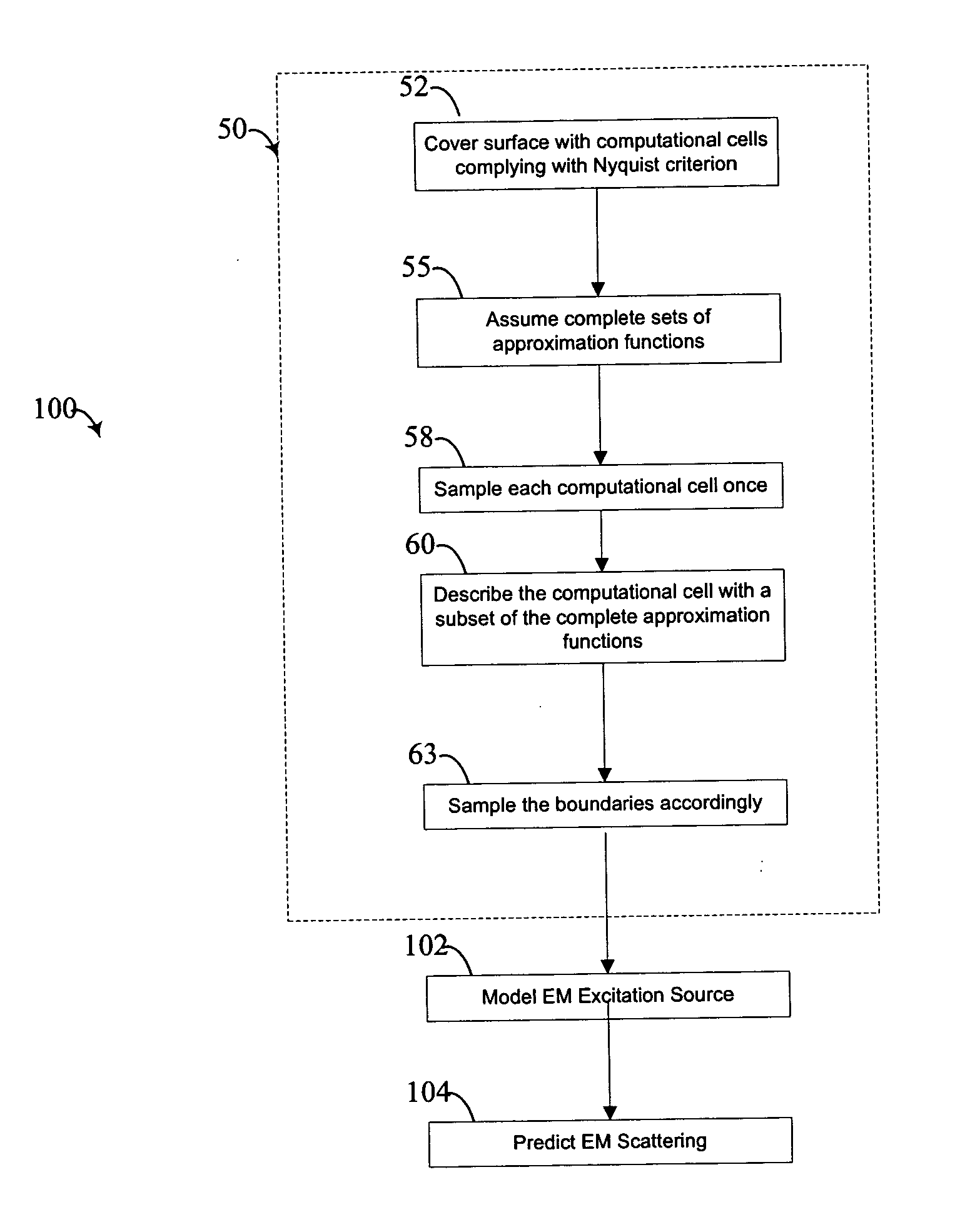
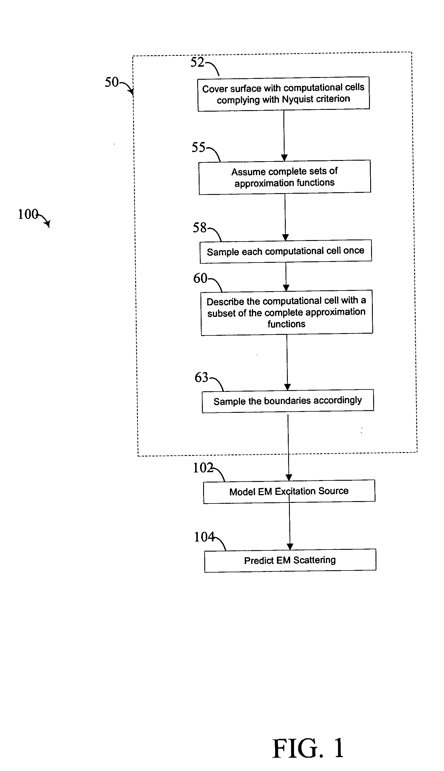
As described more fully below, embodiments of methods and systems in accordance with the present invention incorporate Kirchhoff's First Law into the analytical modeling of a scatterer to provide a simplified analytical model of the scatterer compared with prior art methods. Such embodiments may thereby reduce the description of scattering from an analytic surface to a computation derived by (1) covering the surface with computational cells that comply with Nyquist...


PUM


Abstract

Methods and systems for predicting electromagnetic scattering are disclosed. In one embodiment, a method includes covering at least a portion of an analytical model of a target with computational cells, and formulating a plurality of approximation functions. The formulating of the approximation functions includes simplifying a set of method of moments equations based on Kirchhoff's first law to provide an impedance matrix multiplied by a solution vector equated with a right hand side vector. A plurality of boundary conditions are established for the plurality of approximation functions, and the plurality of approximation functions are solved for the solution vector. The impedance matrix is deflated by a sparse transformation determined by the geometry of the scatterer, independent of material properties and frequency, subsequently reducing the computational complexity of the scattering calculation.

Description

FIELD OF THE INVENTION This invention relates generally to automating electromagnetic scattering predictions and, more specifically, to computer analysis by method of moments. BACKGROUND OF THE INVENTION Various numerical full-wave electromagnetic analysis techniques have been used to characterize electromagnetic scattering by passive arbitrary three-dimensional structures. The analysis is generally based on solving Maxwell's electromagnetic (EM) equations for the surface under analysis. Because of the need to capture the signature response from complex structures, such as aircraft, the analysis has been approximated and automated using the method of moments (MoM) and are well suited to the problem only after characterizing the non-planar surface as consisting of a first mesh of finite planar surfaces or cells on the structure. For example is U.S. Pat. No. 6,353,801 granted to Sercu, et al. on Mar. 5, 2002, or R. Harrington, Origin and Development of the Method of Moments for Fiel...

Claims


Application Information

Patent Timeline
Patent Type & Authority Applications(United States)
IPC IPC(8): G06F17/50H01Q15/02
CPCG06F17/5018H01Q15/02G06F2217/16G06F30/23G06F2111/10
Inventor NACHAMKIN, JACK
Owner THE BOEING CO
Why Eureka
Try Eureka