Systems and methods for collaborative communication

a collaborative communication and communication system technology, applied in the field can solve the problems of inability to provide the best combination of cost, performance, bandwidth usage, and communication links between participants, and achieve the effect of convenient connection of communication devices and networks

Active Publication Date: 2005-03-31
RED HAT
View PDF13 Cites 75 Cited by
  • Summary
  • Abstract
  • Description
  • Claims
  • Application Information

AI Technical Summary

Benefits of technology

[0007] A collaborative communication system comprises a highly flexible architecture that facilitates connecting communication devices and networks to establish collaboration sessions in a manner that allows distribution of various services and features throughout the collaborative communication system to provide scalability and selectable combination of cost, resource usage, and performance.

Problems solved by technology

It may not be desirable, or possible, for all of the participants in a meeting to be in the same physical location at the same time, in which case meeting objectives may be achieved using various communication equipment and networks as tools for facilitating remote collaboration in a multimedia collaboration session.
Thus, the communication links between participants vary greatly in quality, bandwidth, and usage cost.
The server is located at a point in the network topology that is often not optimal for a given session's participants.
Accordingly, it is often not possible to provide the best combination of cost, performance, and bandwidth usage for a session's participants.
This architecture makes central control and coordination difficult, and also limits the size and media capability of the conference, there being no way to perform tasks requiring aggregate media processing, such as audio mixing or video switching between speakers.
Moreover, collaboration systems in use today often limit the performance experienced by all participants to that provided by the slowest network connection.
Other existing systems offer a degree of flexibility in location of components, but are limited to a single media type.

Method used


Image

  • Systems and methods for collaborative communication
  • Systems and methods for collaborative communication
  • Systems and methods for collaborative communication

Examples


Embodiment Construction

.”

BRIEF DESCRIPTION OF THE DRAWINGS

[0009] Features, aspects, and embodiments of the inventions are described in conjunction with the attached drawings, in which:

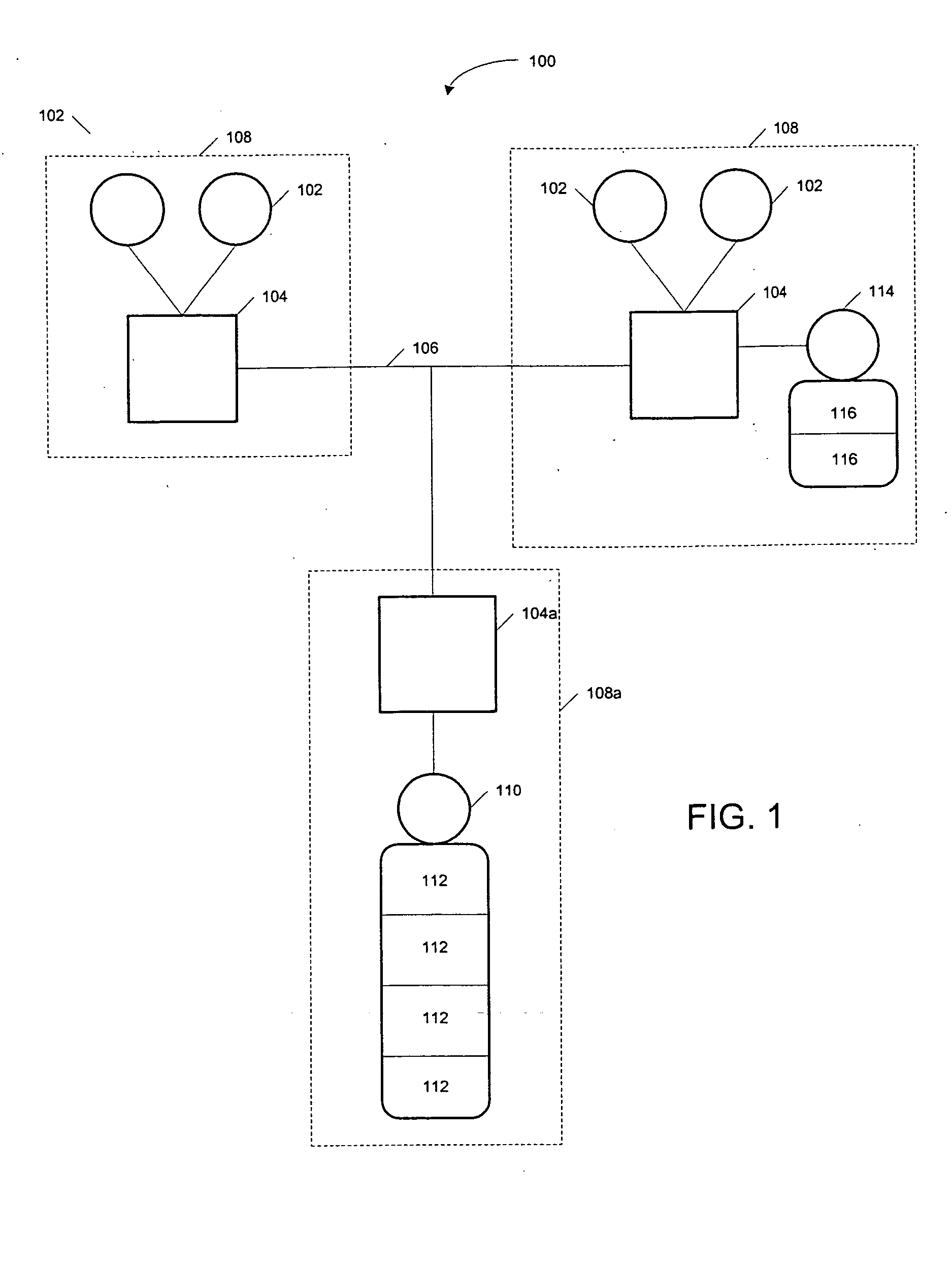
[0010]FIG. 1 is a diagram illustrating an example collaborative communication system configured in accordance with one embodiment of the invention;

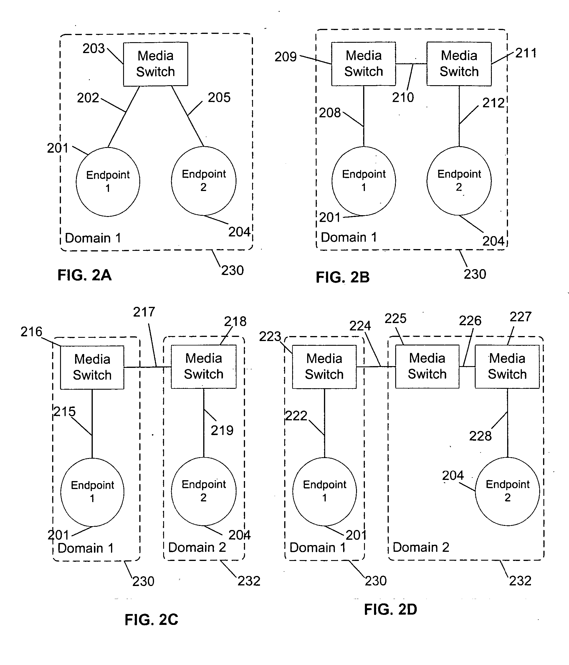
[0011]FIG. 2A is a diagram illustrating the communication of messages within a collaborative communication system where only one media switch is involved in accordance with one embodiment of the invention;

[0012]FIG. 2B is a diagram illustrating the communication of messages within a collaborative communication system where two media switches are involved in accordance with one embodiment of the invention;

[0013]FIG. 2C is a diagram illustrating the communication of messages within a collaborative communication system where two media switch and two domains are involved in accordance with one embodiment of the invention;

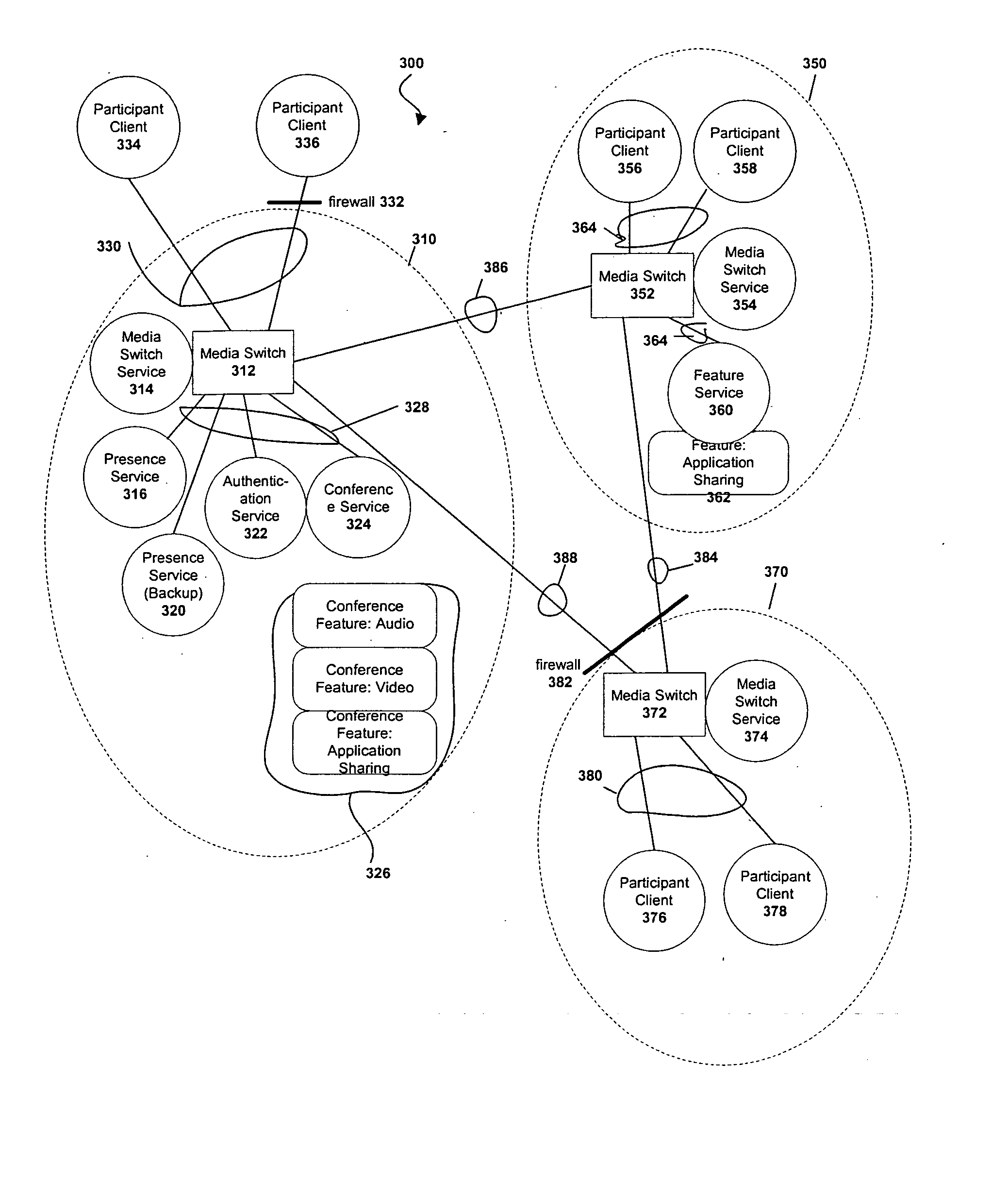
[0014]FIG. 2D is a diagram illustrating the communication ...


PUM


Abstract

A collaborative communication system comprises a highly flexible architecture that facilitates connecting communication devices and networks to establish multimedia collaboration sessions in a manner that allows distribution of various services and features throughout the collaborative communication system to provide scalability and selectable combination of cost, resource usage, and performance.

Description

FIELD OF THE INVENTION [0001] This invention relates generally to the use of communication devices and networks to facilitate human communications and interaction and, more particularly, to facilitate collaborative communication sessions among a plurality of participants. BACKGROUND OF THE INVENTION [0002] In the course of conducting activities involving multiple parties, a need often arises for people to meet to share information, exchange data or documents, discuss topics of mutual interest, or collaborate in preparing various documents or other work product. It may not be desirable, or possible, for all of the participants in a meeting to be in the same physical location at the same time, in which case meeting objectives may be achieved using various communication equipment and networks as tools for facilitating remote collaboration in a multimedia collaboration session. It can be useful for such a session to include a variety of media types that include the participants' voices,...

Claims


Application Information

Patent Timeline
Patent Type & Authority Applications(United States)
IPC IPC(8): G06F15/16H04LH04L12/16H04L12/18H04L29/06
CPCH04L12/1827H04L12/1886H04L65/403H04L63/083H04L29/06027H04L65/1101H04L67/54H04L12/1813H04L67/14H04L12/1818H04L63/08H04L65/1069H04L67/147
Inventor JONES, DANVERNON, TODDPUENTES, EMMANUELWANEK, CHARLESMARCUM, WILLIAM
Owner RED HAT
Why Eureka
Try Eureka