Eureka AIR delivers breakthrough ideas for toughest innovation challenges, trusted by R&D personnel around the world.

Profiling complex surface structures using scanning interferometry

Active Publication Date: 2005-04-07
ZYGO CORPORATION
View PDF41 Cites 113 Cited by
  • Summary
  • Abstract
  • Description
  • Claims
  • Application Information

AI Technical Summary

Benefits of technology

After the complex surface structure is characterized, surface height can be efficiently determined. For example, a cross-correlation between the scanning interferometry signal and a model signal having the shape corresponding to the complex surface structure can produce a peak at a scan coordinate corresponding to the surface height. Similarly, in the frequency domain, a phase contribution resulting from the complex surface structure can be subtracted from the frequency domain phase profile and the surface height can be extracted using a conventional FDA analysis.

Problems solved by technology

Unfortunately such assumptions may break down when applied to a test object having a thin film because of reflections by the top surface and the underlying film / substrate interface.

Method used


Image

  • Profiling complex surface structures using scanning interferometry
  • Profiling complex surface structures using scanning interferometry
  • Profiling complex surface structures using scanning interferometry

Examples


Embodiment Construction

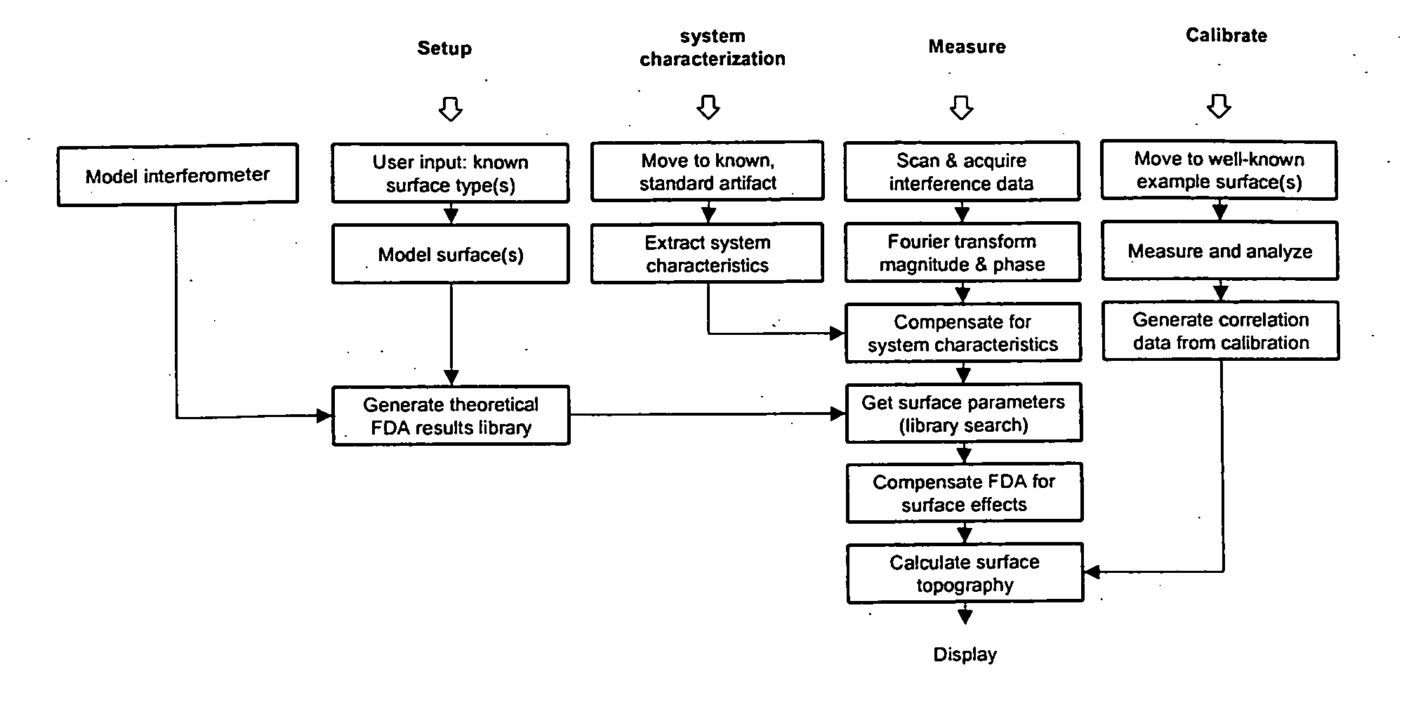
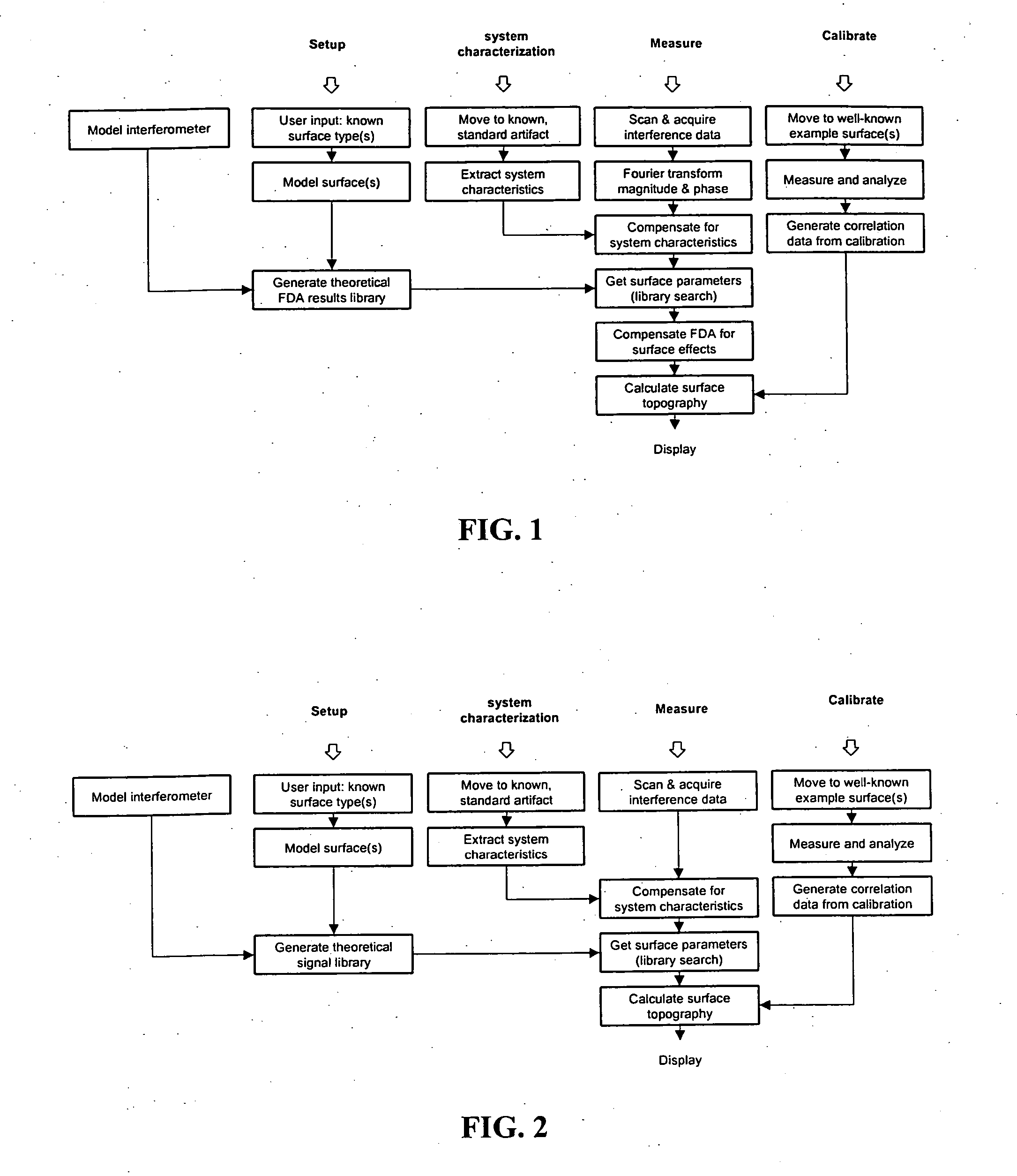
FIG. 1 shows a flow chart that generally describes one embodiment of the invention in which the analysis of the scanning interferometry data is performed in the spatial frequency domain.

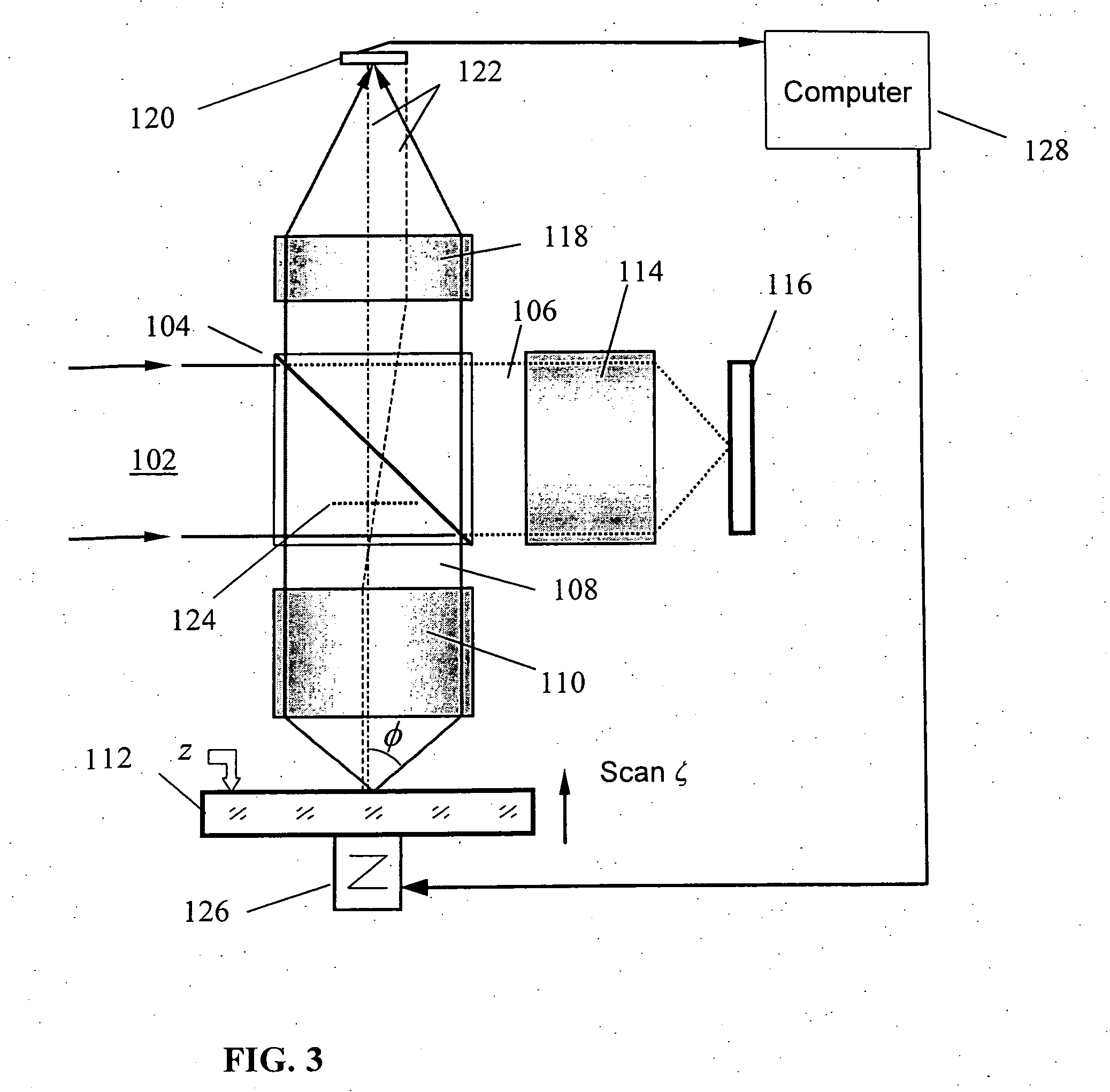
Referring to FIG. 1, to measure data from a test object surface an interferometer is used to mechanically or electro-optically scan the optical path difference (OPD) between a reference and measurement path, the measurement path being directed to an object surface. The OPD at the beginning of the scan is a function of the local height of the object surface. A computer records an interference intensity signal during the OPD scan for each of multiple camera pixels corresponding to different surface locations of the object surface. Next, after storing interference intensity signal as a function of OPD scan position for each of the different surface locations, the computer performs a transform (e.g., a Fourier Transform) to generate a frequency-domain spectrum of the signal. The spectrum contains both m...


PUM


Abstract

A method including comparing information derivable from a scanning interferometry signal for a first surface location of a test object to information corresponding to multiple models of the test object, wherein the multiple models are parametrized by a series of characteristics for the test object. The derivable information being compared may relate to a shape of the scanning interferometry signal for the first surface location of the test object.

Description

BACKGROUND The invention relates to using scanning interferometry to measure surface topography and / or other characteristics of objects having complex surface structures, such as thin film(s), discrete structures of dissimilar materials, or discrete structures that are underresolved by the optical resolution of an interference microscope. Such measurements are relevant to the characterization of flat panel display components, semiconductor wafer metrology, and in-situ thin film and dissimilar materials analysis. Interferometric techniques are commonly used to measure the profile of a surface of an object. To do so, an interferometer combines a measurement wavefront reflected from the surface of interest with a reference wavefront reflected from a reference surface to produce an interferogram. Fringes in the interferogram are indicative of spatial variations between the surface of interest and the reference surface. A scanning interferometer scans the optical path length differenc...

Claims


Application Information

Patent Timeline
IPC IPC(8): G01B9/02G01B11/06G01N21/95
CPCG01B11/0675G01N21/9501G01B9/0201G01B9/02057G01B9/0209G01N21/8422G01B9/02084G01B9/02088G01B2290/50G01B9/02072G01N21/211G01B2290/70
Inventor DE GROOT, PETER J.STONER, ROBERTDE LEGA, XAVIER COLONNA
Owner ZYGO CORPORATION
Why Eureka
Eureka Blog
Learn More