

Starter having excessive-torque-absorbing device
- Summary
- Abstract
- Description
- Claims
- Application Information
AI Technical Summary
Benefits of technology
Problems solved by technology
Method used
Image

Examples
first embodiment
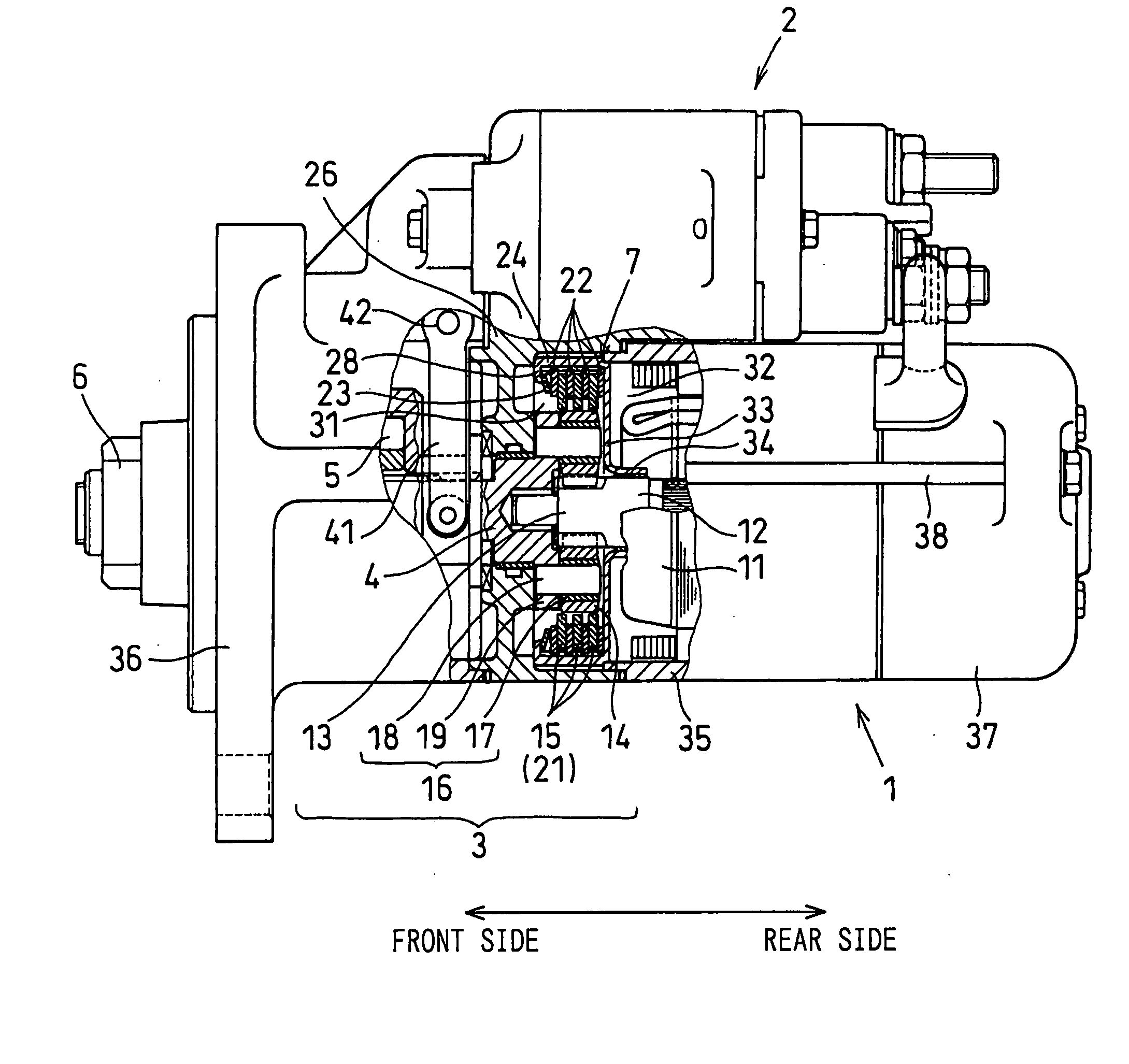
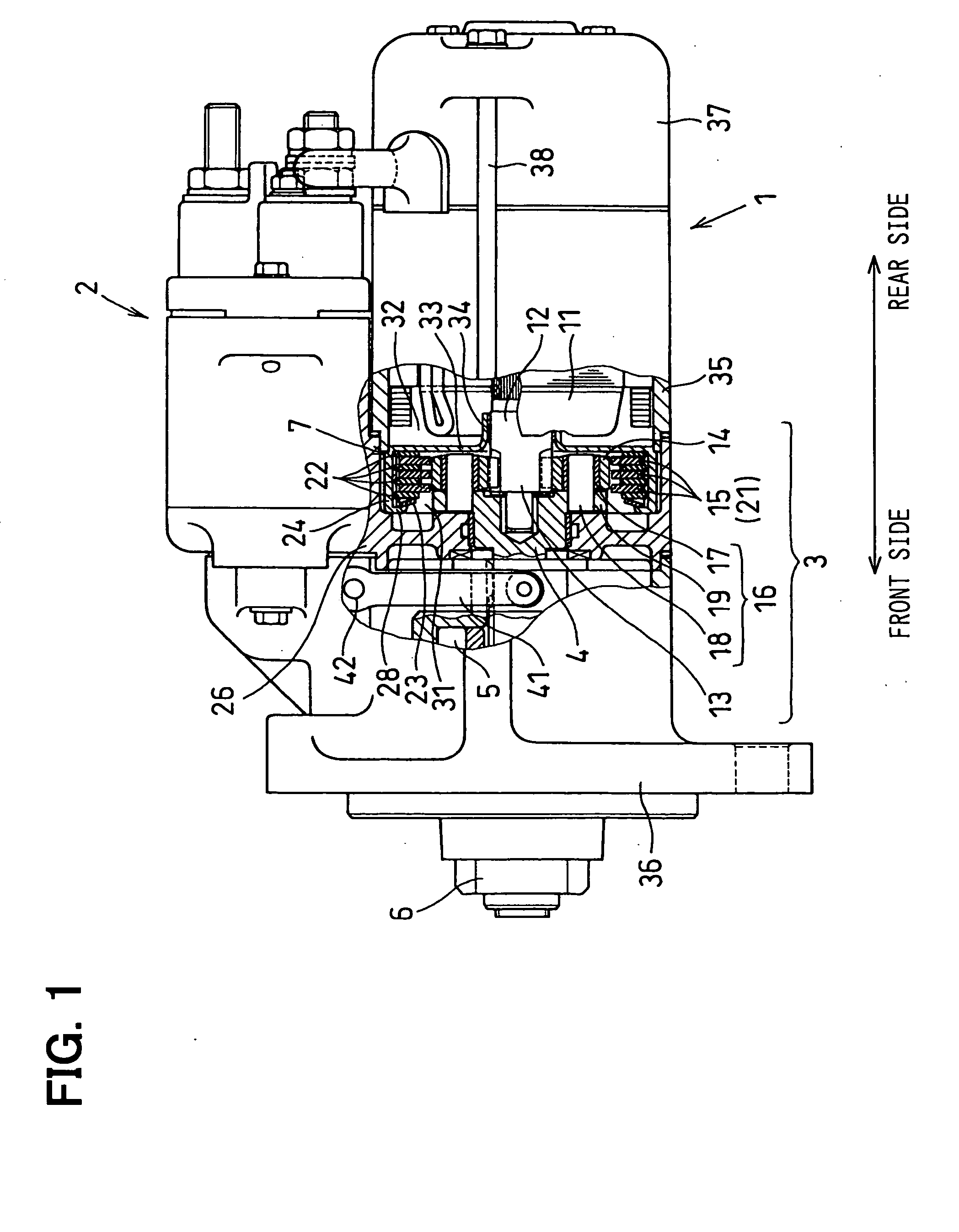
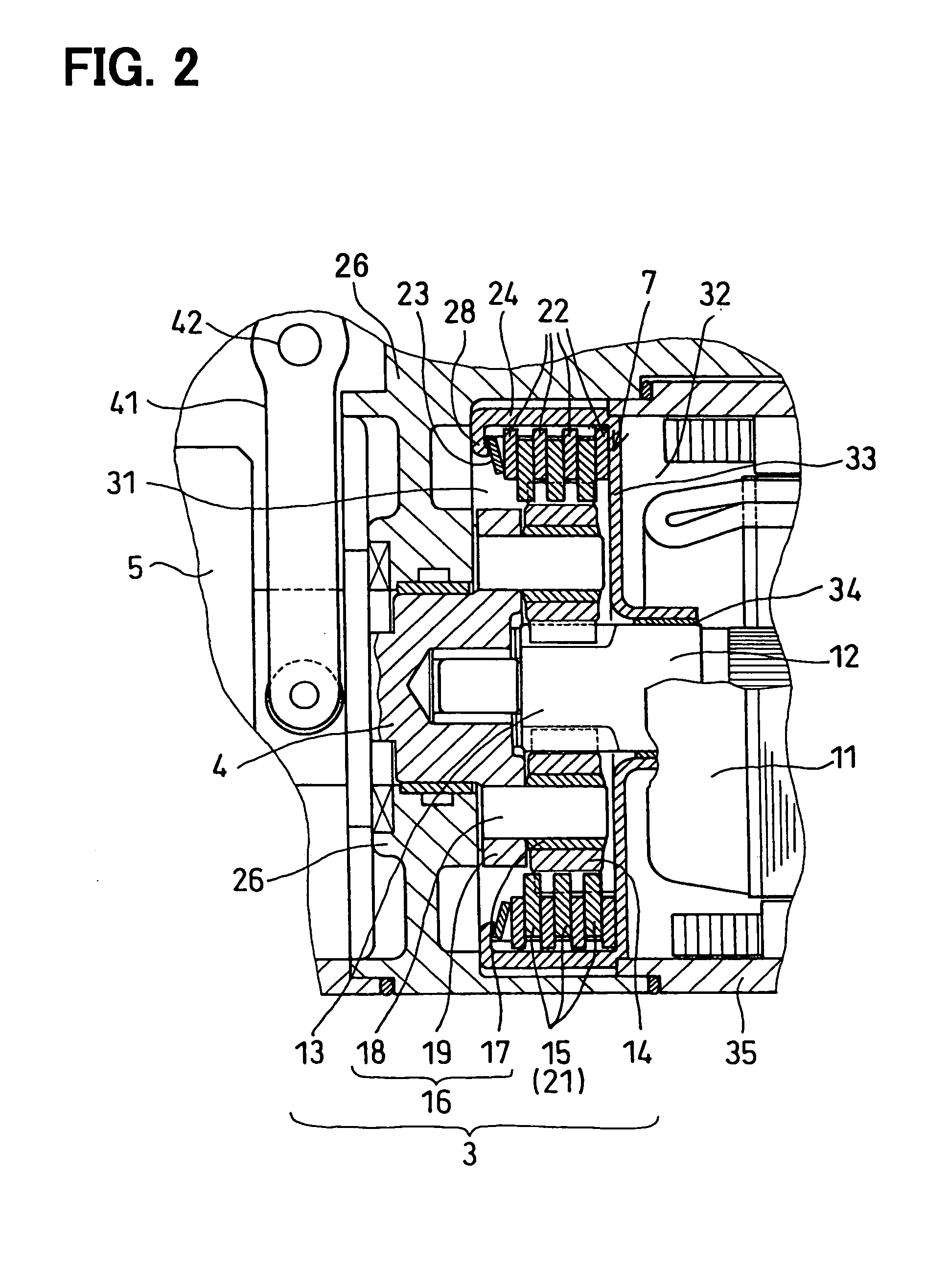
[0022] the present invention will be described with reference to FIGS. 1-6B. A starter for cranking an internal combustion engine is composed of: an electric motor 1, a magnetic switch 2 for controlling electric power to be supplied to the electric motor 1 in an On-OFF fashion; a planetary gear speed reduction device 3 for reducing a rotational speed of the electric motor 1; an output shaft 4 to which a rotational torque of the electric motor 1 is transmitted after the rotational speed is reduced by the planetary gear speed reduction device 3; a one-way clutch 5 disposed on the output shaft 4; a pinion gear 6 to which a rotational torque of the output shaft 4 is transmitted via the one-way clutch 5; a device 7 for absorbing an excessive torque imposed on the starter; and other associated components.
[0023] As shown in FIG. 1, the front side of the starter is covered with a front housing 36, and the rear side of the starter is covered with a rear housing 37. A center housing 26 contai...
second embodiment
[0040] the present invention will be described with reference to FIG. 7. In this embodiment, the thickness of the rotatable disk 21 is different from that of the first embodiment. Other structures and functions are the same as those of the first embodiment. As shown in FIG. 7, the radial inside portion of the rotatable disk 21 where the internal gear 15 is formed is made thicker than the radial outside portion that serves as the friction surface. That is, the thickness “A” of internal gear tooth is thicker than the thickness “B” of the radial outside portion. In this manner, the total width of the internal gear 15 can be made large. By increasing the width of the internal gear 15, a pressure imposed on the tooth surface (a tooth surface pressure) can be reduced, and thereby abrasion wear of the internal gear 15 can be reduced. Though the thickness difference between A and B is made symmetrically with respect to the thickness center of the rotatable disk 21 in the embodiment shown in...
PUM
 Abstract
Description
Claims
Application Information