Apparatus and method for reducing hydrofoil cavitation

a technology of apparatus and hydrofoil, applied in the direction of special-purpose vessels, vessel construction, transportation and packaging, etc., can solve the problems of sapping the ship and rudder's momentum, significant drag in the boundary layer, etc., to reduce turbulence close, increase the speed of passing water, and reduce the effect of turbulence and eddies

Inactive Publication Date: 2005-04-14
HILLEMAN TERRY BRUCEMAN
View PDF76 Cites 14 Cited by
  • Summary
  • Abstract
  • Description
  • Claims
  • Application Information

AI Technical Summary

Benefits of technology

[0026] The less efficient perforated propeller is a trade-off for less cavitation. Increasing propeller pitch also trades efficiency for reduced cavitation; this latter trade-off is well known in the art. Cavitation reduction is advantageous for stealth. In the perforated propeller application, the holes should have smooth rounded edges and should be large enough to avoid biologic blockage, yet be small enough to interfere with efficiency as little as possible. They should be located wherever cavitation is a problem, e.g. ahead of the pitting to avoid cavitation inception. The same may be generally said of the perforated rudder (or any submerged hydrofoil); however, efficiency may be less of a concern, while strength may be more of a concern. A rudder with staggered rounded perforations is nearly as strong as a solid rudder. Any perforation pattern would apply; some examples would be staggered round holes, staggered teardrops, or parallel longitudinal slits running the length of the chord. The longitudinal slits running the length of the chord reduce boundary layer turbulence (as well as cavitation) extremely well. All have the advantage of markedly reducing boundary layer turbulence as well as controlling cavitation on the suction side; they also reduces weight without significantly affecting performance strength.
[0033] Suction turbulence is present at the trailing edge. The trailing edge is often rounded to minimize cavitation, as a sharp trailing edge can lead to cavitation at lower speeds. The golf-ball dimple effect, the coarser longitudinal ridges, or the larger fish scale texturing would be of great advantage in this location, as they would pressurize the rounded trailing edge. In addition, the golf ball dimpling effect could be incorporated in Dr. Shen's tip plate design, for example, dimpling the rounded rudder tab at the lower end tip would pressurize a greater portion of it's rounded trailing end.

Problems solved by technology

Boundary layer drag can be significant in turbulent water; it is a significant cause of submarine cavitation.
On a well-trimmed rudder, these drag forces act on the rudder; they worsen as rudder alignment worsens.
Surface drag is due to viscous shear forces of the moving water against the surface of the ship and rudder, resulting in eddies and turbulence that cause deceleration, sapping the ship and rudder's momentum.

Method used


Image

  • Apparatus and method for reducing hydrofoil cavitation
  • Apparatus and method for reducing hydrofoil cavitation
  • Apparatus and method for reducing hydrofoil cavitation

Examples


Embodiment Construction

[0037] The present invention will be described as it applies to its preferred embodiment. It is not intended that the present invention be limited to the described embodiment. It is intended that the invention cover all modifications and alternatives, which may be included within the spirit and scope of the invention.

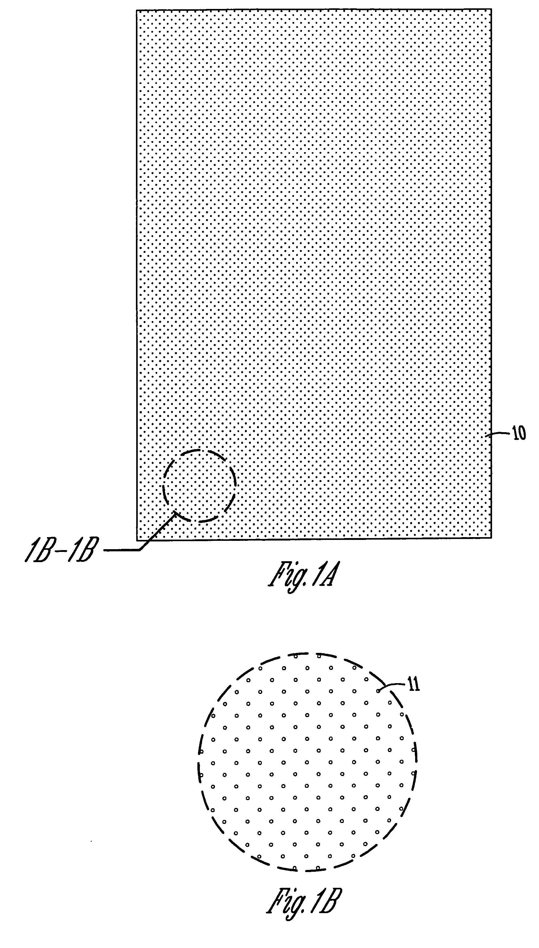
[0038] Referring to FIG. 1, FIG. 1A describes an embodiment in which the entire rudder 10 is covered by alternating round-hole perforations 11, as magnified in 1B. The technique of drilling holes is well known in the art. In this case the rounded perforations would result in a dimpled surface (FIG. 3A), capable of evenly pressurizing the suction side as well as augmenting surface turbulence and reducing boundary layer drag on the pressure side (from water passage through the holes).

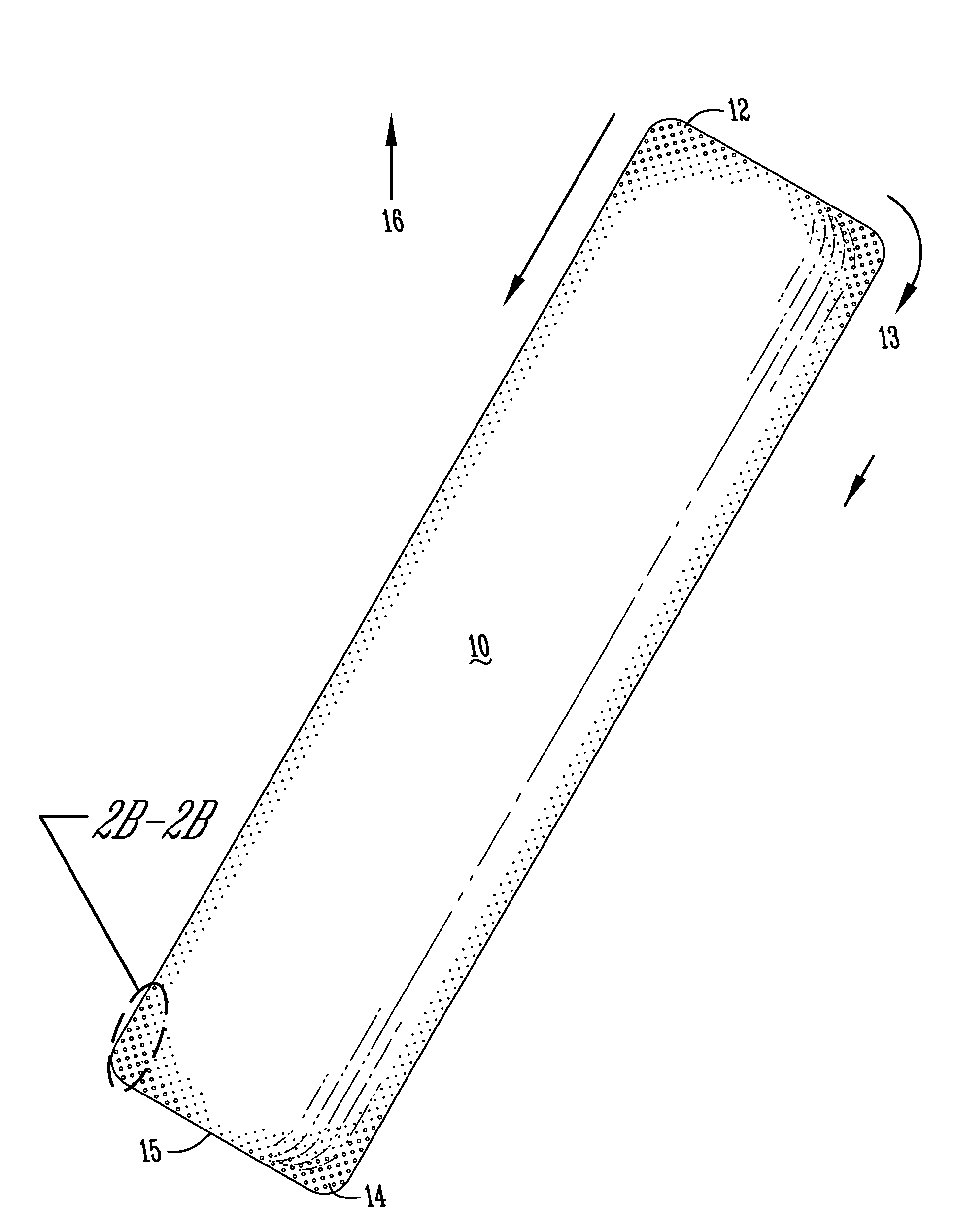
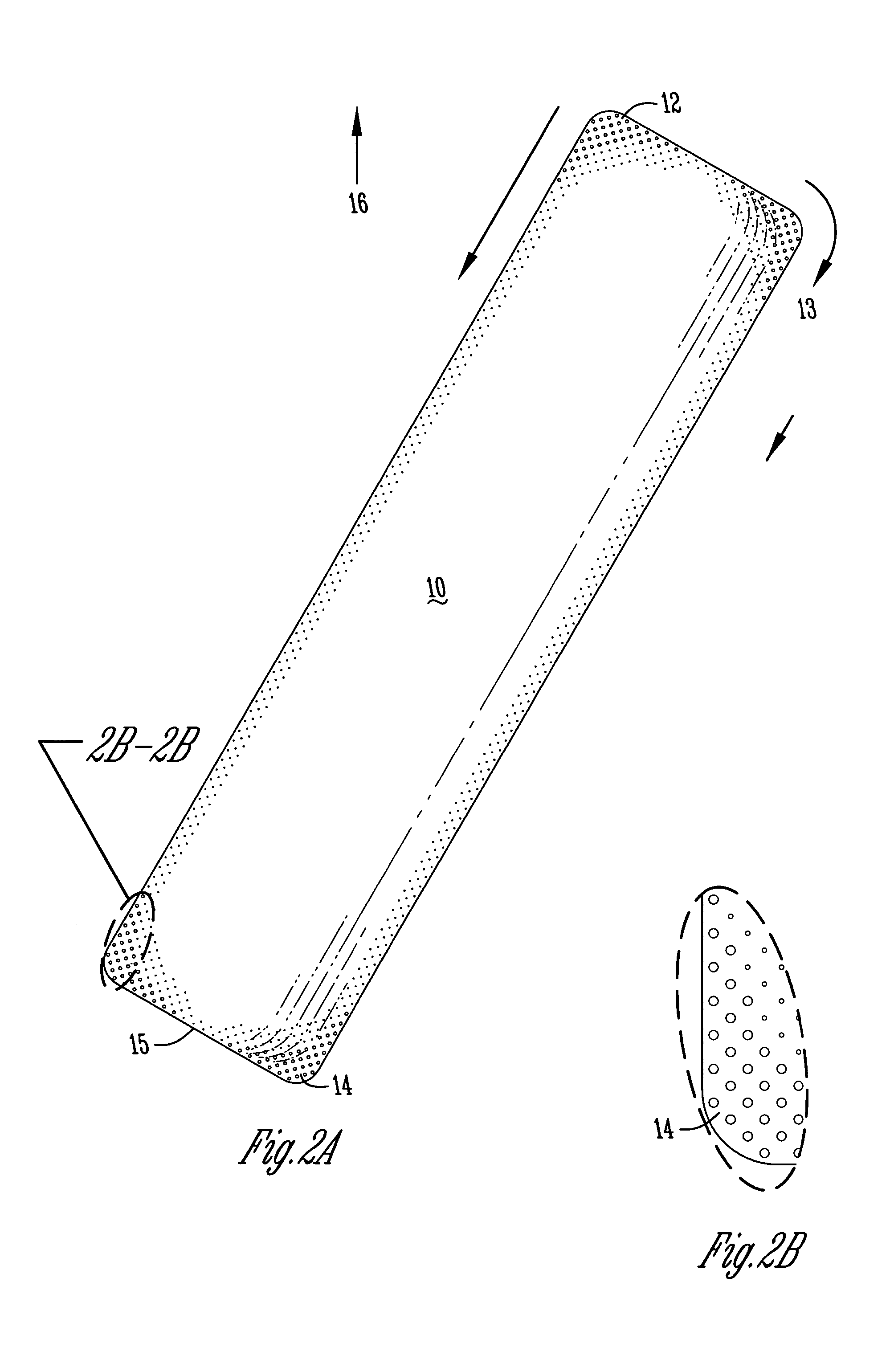
[0039] In the FIG. 2 bottom rudder view, this embodiment illustrates surface texture minimizing leading edge cavitation and trailing edge cavitation, without perforations. Rudder 10 has a l...


PUM


Abstract

A method of reducing underwater hydrofoil cavitation is described; hydrofoil steering vanes trade a small degree of efficiency for significant cavitation reduction, through perforations in the hydrofoil. Some pattern examples are discussed. A method of further cavitation reduction through surface texture variation also reduces underwater hydrofoil drag; some patterns are discussed. Combining the methods provides maximum cavitation reduction.

Description

CROSS-REFERENCE TO RELATED APPLICATIONS [0001] This non-provisional application claims the benefit of U.S. Provisional Patent Application Ser. No. 60 / 417,127, filed Oct. 10, 2002, as well as the benefit of U.S. patent application Ser. No. 10 / 164,730 filed Jun. 6, 2002, the benefit of U.S. patent application Ser. No. 10 / 171,273 filed Jun. 12, 2002, the benefit of Provisional Application Ser. No. 60 / 297,314 filed Jun. 12, 2001, the benefit of U.S. Provisional Application Ser. No. 60 / 361,950 filed Mar. 7, 2002, and the benefit of U.S. patent application Ser. No. 09 / 718,753 filed on Nov. 22, 2000, now issued as U.S. Pat. No. 6,427,618 for all that they contain and teach.BACKGROUND OF THE INVENTION [0002] 1. Field of the Invention [0003] The present invention relates to rudders (and other underwater hydrofoils) for aquatic vessels and more particularly to a rudder (or any submerged hydrofoil) and methods for minimizing early cavitation. It also has applications for fluid pumps or turbine...

Claims


Application Information

Patent Timeline
Patent Type & Authority Applications(United States)
IPC IPC(8): B63B1/24
CPCY02T70/121B63B1/248Y02T70/10
Inventor HILLEMAN, TERRY BRUCEMAN
Owner HILLEMAN TERRY BRUCEMAN
Why Eureka
Try Eureka