Engine valve moving device

Inactive Publication Date: 2005-04-14
YAMAHA MOTOR CO LTD
View PDF5 Cites 17 Cited by
  • Summary
  • Abstract
  • Description
  • Claims
  • Application Information

AI Technical Summary

Benefits of technology

[0006] According to a first aspect of the invention, there is provided an engine valve train device in which an intermediate driven wheel disposed in the vicinity of a camshaft is driven by a crankshaft-side driving wheel formed on a crankshaft and a camshaft gear fixed to the camshaft is driven by an intermediate gear fixed to the intermediate driven wheel, the engine valve train device being characterized in that the intermedi

Problems solved by technology

Note that in case a construction is adopted in which an intermediate gear is disposed in front of an intermediate sprocket (for example, refer to JP-A-9-250314), while the valve timing work becomes easy to be carried out, a dimensi

Method used


Image

  • Engine valve moving device
  • Engine valve moving device
  • Engine valve moving device

Examples


Embodiment Construction

[0034] Hereinafter, an embodiment of the invention will be described with reference to the accompanying drawings.

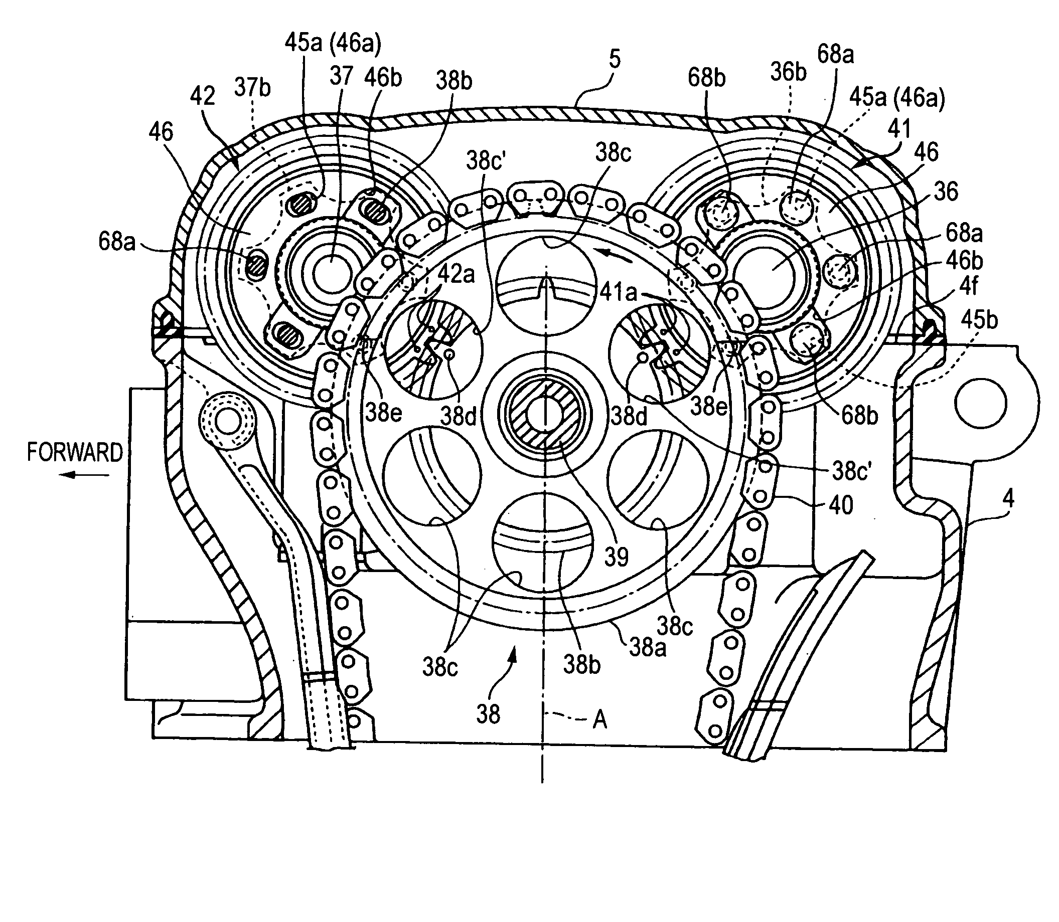
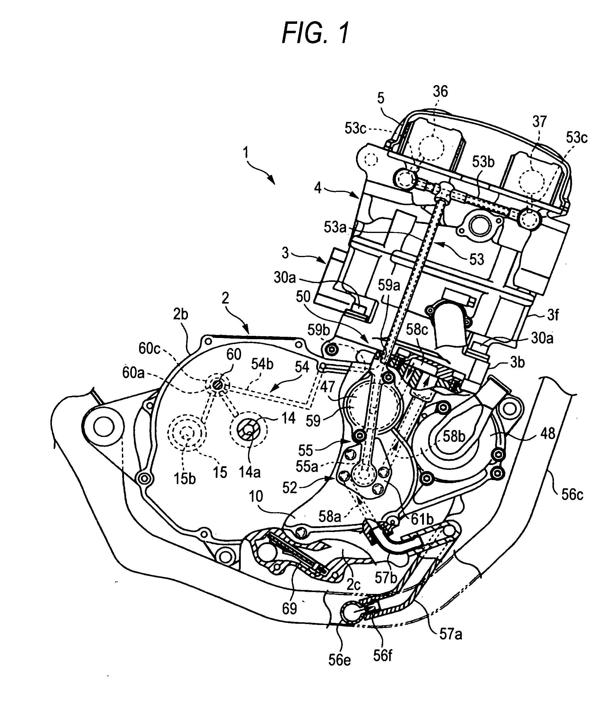
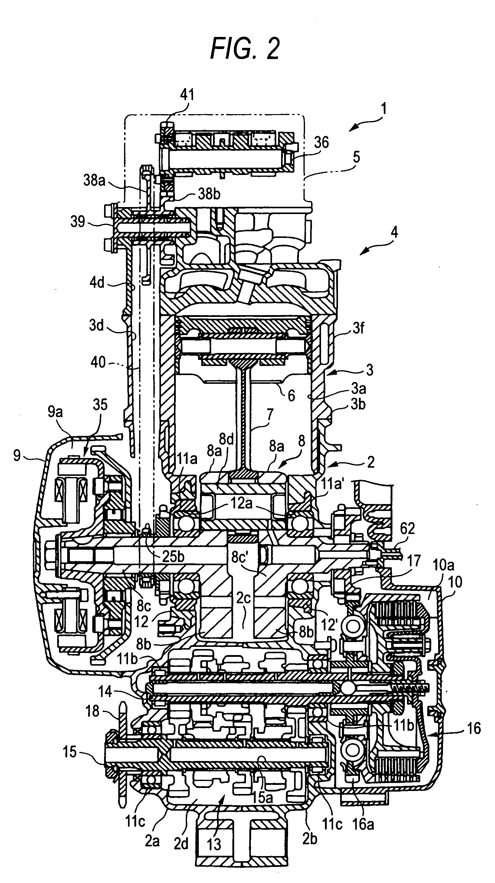
[0035] FIGS. 1 to 21 are drawings for describing an embodiment of the invention. In the drawings, reference numeral 1 denotes a water-cooled, 4-cycle, single cylinder, 5-valve engine, and in general, the engine has a construction in which a cylinder body 3, a cylinder head 4 and a cylinder head cover 5 are stacked on and fastened to a crankcase 2, and a piston 6 slidably disposed in a cylinder bore 3a in the cylinder body 3 is connected to a crankshaft 8 via a connecting rod 7.

[0036] The cylinder body 3 and the crankcase 2 are securely connected together by screwing four case bolts 30a which pass through a lower flange portion (a case side flange portion) 3b into a cylinder side mating surface 2e of the crankcase 2. To be more specific, the case bolts 30a are screwed into bolt connecting portions (connecting boss portions) 12c of iron alloy bearing brackets (bearing mem...


PUM


Abstract

In an engine valve train device in which a crankshaft sprocket 25b provided on a crankshaft 8 and an intermediate sprocket 38a disposed in the vicinity of camshafts 36, 37 are connected by means of a timing chain 40 and an intermediate gear 38b fixed to the intermediate sprocket 38a is made to mesh with camshaft gears 41, 42 fixed to the camshafts, the intermediate gear 38b is made smaller in diameter than the intermediate sprocket 38a and is disposed behind the intermediate sprocket 38, and furthermore, an inspection hole 38c′ is formed in the intermediate sprocket 38a for visualizing the meshing portion between the intermediate gear 38b and the camshafts gears 41, 42.

Description

TECHNICAL FIELD [0001] The present invention relates to an engine valve train device in which a camshaft is driven to rotate by a crankshaft. BACKGROUND ART [0002] For example, as valve train devices for motorcycle engines, there exists conventionally a valve train device having a construction in which a crankshaft sprocket provided on a crankshaft and an intermediate sprocket disposed in the vicinity of a camshaft are connected by way of a timing chain, so that an intermediate gear fixed to the intermediate sprocket meshes with a camshaft gear fixed to the camshaft (for example, refer to JP-A-6-66111). [0003] In the case of the construction in which the intermediate gear fixed to the intermediate sprocket is brought into mesh engagement with the camshaft gear, while a construction in which timing or alignment marks on the intermediate gear and the camshaft gear are caused to align with each other is adopted as a construction for carrying out valve timing, since the construction of ...

Claims


Application Information

Patent Timeline
IPC IPC(8): F01L1/02F01L1/46F02B61/02F02B67/06F02B75/02F02B75/16
CPCF01L1/02F02B2275/18F01L1/024F01L1/026F01L1/46F01L2001/0537F01L2003/251F01L2101/00F01L2103/01F01L2103/02F01L2810/04F02B61/02F02B67/06F02B75/16F02B2075/027F01L1/022F01L2303/02F01L2303/01F01L2301/00
Inventor UTSUMI, YOJIITO, MASAHIRO
Owner YAMAHA MOTOR CO LTD
Why Eureka
Try Eureka