Shielded flat cable
a flat cable and shielding technology, applied in the direction of flat/ribbon cables, insulated conductors, cables, etc., can solve the problem of increasing the wiring space needed for shielded flat cables, and achieve the effect of preventing the breakage of the conductors enhancing the transmission characteristics of the signal wires
- Summary
- Abstract
- Description
- Claims
- Application Information
AI Technical Summary
Benefits of technology
Problems solved by technology
Method used
Image

Examples
first embodiment
[0035] Hereinafter, a description will be made of a comparison between examples of shielded flat cables of the first embodiment and an example of a conventional shielded flat cable.
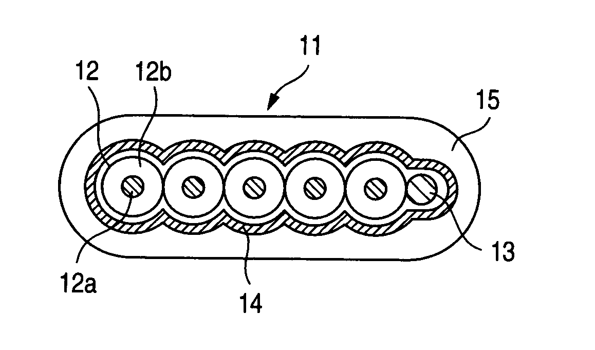
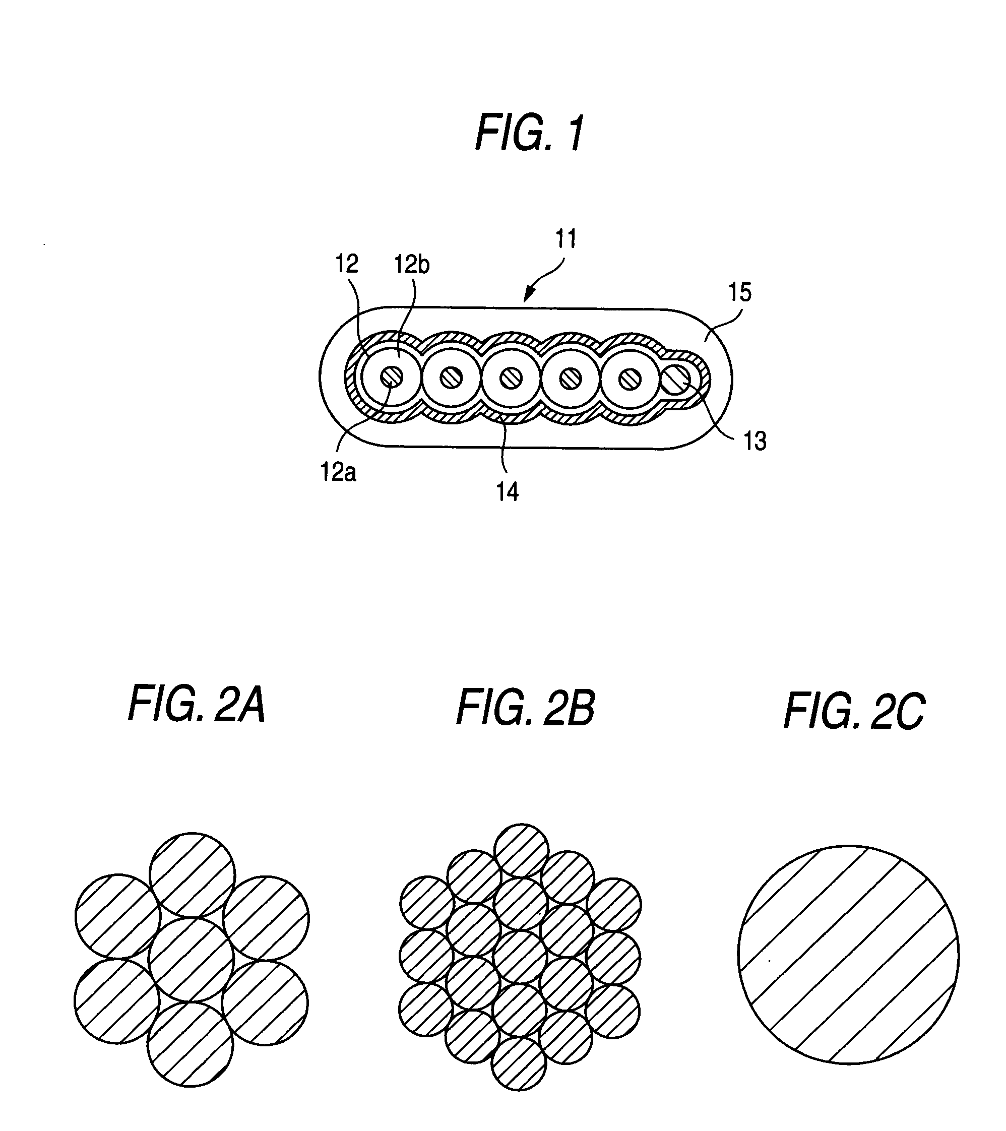
[0036] A first product (product 1) according to the first embodiment is made with the following characteristics. [0037] shielded flat cable 11; [0038] width: 3.94 mm, thickness: 1.98 mm [0039] two signal wires 12; [0040] material for conductor 12a: Cu—Ag, conductor size: 0.08 mm2, 7-wire stranded type, material for insulating coating layer 12b: foamed polyethylene, outer diameter of each signal wire: 1.35 mm [0041] drain wire 13; [0042] material: Sn-plated copper, conductor size: 0.22 mm2 [0043] shielding layer 14; [0044] material: copper foil, thickness: 15 μM [0045] insulating sheath 15; [0046] material: halogen-free material, thickness: 0.3 mm.
[0047] A second product (product 2) according to the first embodiment is made with the following characteristics. [0048] shielded flat cable 11; [0049] width: 3...
second embodiment
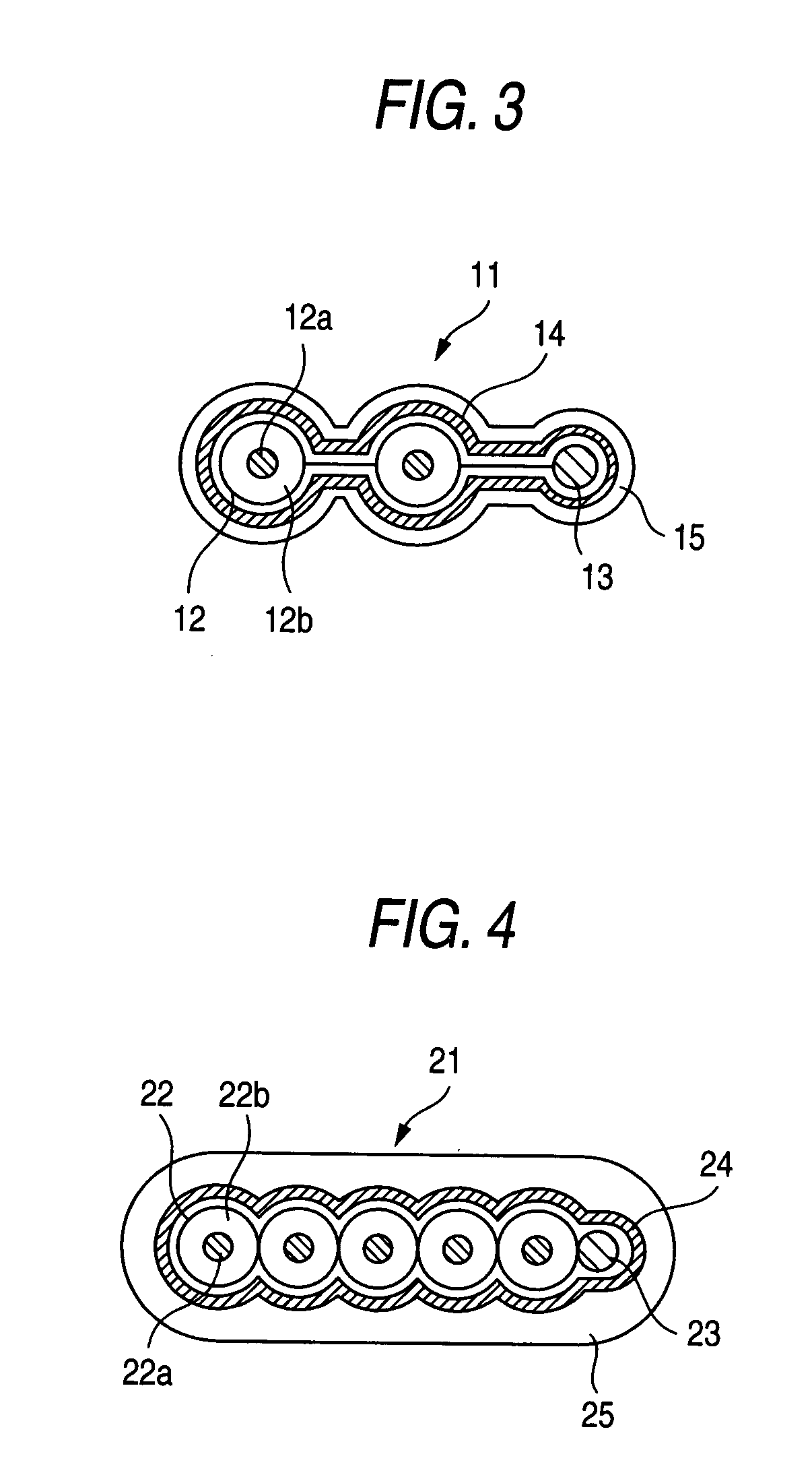
[0081] In the second embodiment, as shown in FIGS. 5A and 5B, the central wire element 22a′ made of copper is disposed straight, and the peripheral wire elements 22a″ made of a copper alloy are twisted around the central wire element 22a′ therealong. The peripheral wire elements 22a″ has a certain amount of margin in length direction whereas the central wire element 22a′, disposed straight, has less amount of margin in length direction than the peripheral wire elements 0.22a″. Therefore, when the shielded flat cable is pulled in length direction, the central wire element 22a′ is most liable to be cut and becomes disconnected first, and therefore copper which is most liable to be extended is used to form the central wire element 22a′. The peripheral wire elements 22a″ (which are made of the copper alloy having a high tensile strength and a high strength) are arranged around the central wire element 22a′ to provide the twisted-wire structure, and by doing so, the well-balanced structu...
PUM
| Property | Measurement | Unit |
|---|---|---|
| sectional area | aaaaa | aaaaa |
| area | aaaaa | aaaaa |
| tensile strength | aaaaa | aaaaa |
Abstract
Description
Claims
Application Information
 - R&D
- Intellectual Property
- Life Sciences
- Materials
- Tech Scout
- Unparalleled Data Quality
- Higher Quality Content
- 60% Fewer Hallucinations
Browse by: Latest US Patents, China's latest patents, Technical Efficacy Thesaurus, Application Domain, Technology Topic, Popular Technical Reports.
© 2025 PatSnap. All rights reserved.Legal|Privacy policy|Modern Slavery Act Transparency Statement|Sitemap|About US| Contact US: help@patsnap.com