Apparatus and method for maneuvering objects in low/zero gravity environments

a technology of electromagnetic force and objects, applied in the field of rockets, orbital transfers and satellite stationkeeping, can solve the problem of limiting the performance of rockets through rocket equations, and achieve the effect of efficient orbital injection and ejection

Active Publication Date: 2005-04-14
SCHUBERT PETER J
View PDF6 Cites 11 Cited by
  • Summary
  • Abstract
  • Description
  • Claims
  • Application Information

AI Technical Summary

Benefits of technology

A significant advantage of this invention is that maneuvering of an object can be exclusively performed using electromagnetic forces, which offer numerous advantages over chemically-fueled and electrostatically-accelerated rockets. The invention achieves efficient orbital injection and ejection without the need for chemical rockets, and can be adapted to use inexhaustible solar energy and / or harvest energy from decelerating / deflecting objects. The invention is adapted to perform either or both of two general classes of orbital maneuver, namely, altering the speed or trajectory of an object. The first class encompasses catching (decelerating) and launching (accelerating) objects, while the second involves deflecting an object, such as forcing an object into or out of an orbital path. In combination, the invention provides a general purpose orbital transfer system and method. For example, a payload launched from the Moon can be deflected into a geosynchronous orbit around the Earth, and then ejected from orbit and accelerated back to the Moon. Fine control over the electromagnetic forces employed in these maneuvers is possible through control circuitry with feedback sensors, such that objects can be delivered, captured and placed in orbit with precision.

Problems solved by technology

Chemically-fueled rockets require that fuel be brought along, and this limits the performance of the rocket through the rocket equation.

Method used


Image

  • Apparatus and method for maneuvering objects in low/zero gravity environments
  • Apparatus and method for maneuvering objects in low/zero gravity environments
  • Apparatus and method for maneuvering objects in low/zero gravity environments

Examples


Embodiment Construction

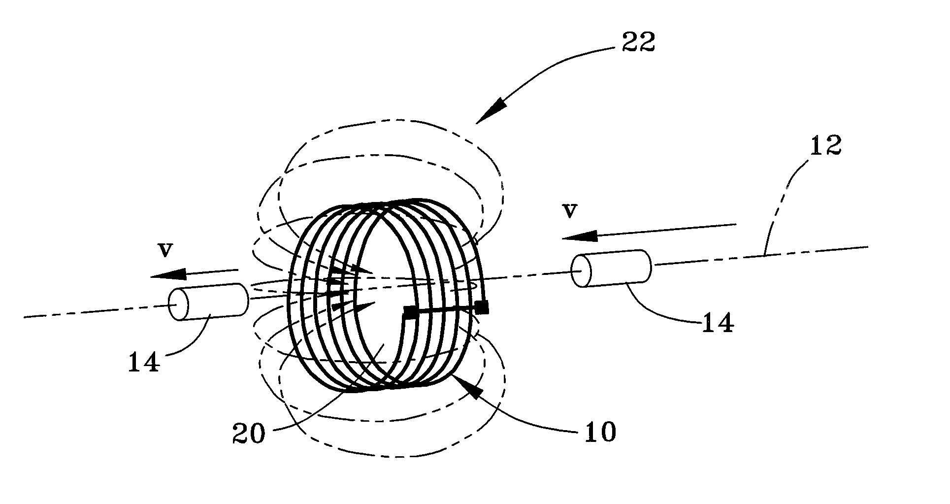
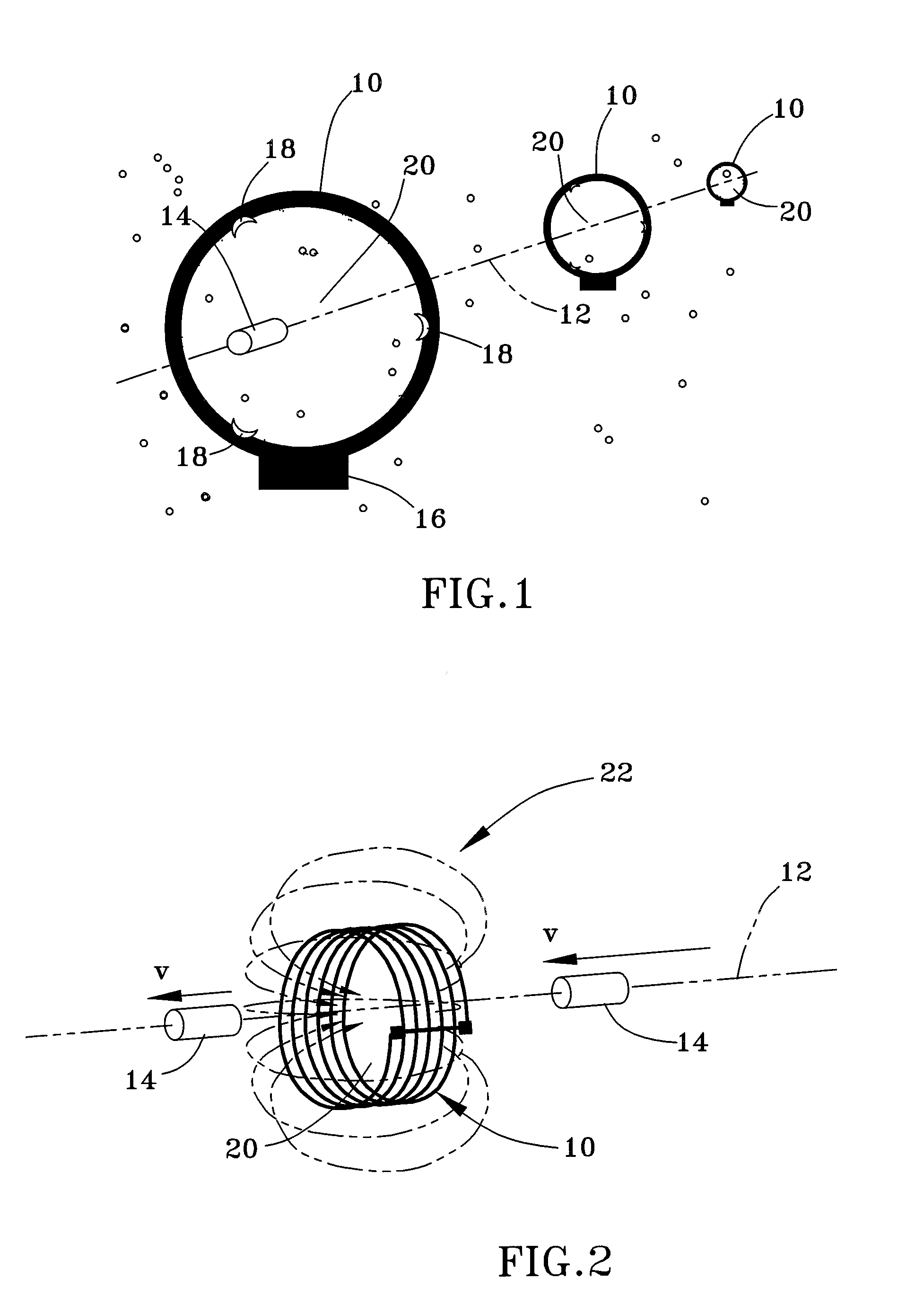
General concepts of the invention can be described in reference to FIG. 1, which depicts three orbiting conductive rings or coils 10 aligned in a substantially straight line along the trajectory 12 of a traveling object, which may be a canister, projectile, vessel, etc., hereafter simply referred to as a payload 14. The coils 10 are represented as being generally annular-shaped, though other shapes are possible. The term “coil” is used herein as any structure capable of producing a magnetic field, and may be a single loop or a winding of multiple concentric loops, as will be evident from the Figures. The magnetic fields produced by the coils 10 are generated with the intent to exert an electromagnetic force on the moving payload 14. The payload 14 is adapted to electromagnetically interact with the magnetic fields, and therefore is formed to contain a ferrous material, hold a static charge, or contain an electromagnet, e.g., superconducting or electric with control circuitry and so...


PUM


Abstract

An apparatus and method that make use of electromagnetic energy to maneuver an object, such as stop, slow, and/or divert a vessel or projectile in low and zero-gravity environments. The apparatus comprises an element capable of generating a magnetic field in the zero or low-gravity environment, and an object capable of electromagnetically interacting with the magnetic field so that the object's speed and/or trajectory is altered when moving in proximity to the magnetic-field generating element. As such, the method entails maneuvering an object in a zero or low-gravity environment by generating a magnetic field in the zero or low-gravity environment, and then moving the object in proximity to the magnetic field such that the magnetic field alters the trajectory and/or speed of the object.

Description

BACKGROUND OF INVENTION 1. Field of the Invention The present invention generally relates to the general field of rocketry, orbital transfers and satellite station-keeping, as well as space vessel attitude control. More particularly, this invention relates to an apparatus and method for maneuvering objects in low and zero-gravity environments using electromagnetic forces. 2. Description of the Related Art The current state of the art in orbital transfers and station keeping involve reaction rockets using a variety of fuels, either chemical or electrostatic acceleration. Chemically-fueled rockets require that fuel be brought along, and this limits the performance of the rocket through the rocket equation. ΔV=lsp·g·ln(Mo / Mf) where ΔV is the velocity change given the specific impulse of the rocket motor (Isp), the gravitational constant (g), and the logarithm of the ratio of weights before (Mo) and after (Mf) the burn. It would be desirable if alternative techniques were availabl...

Claims


Application Information

Patent Timeline
Patent Type & Authority Applications(United States)
IPC IPC(8): B64G1/32B64G1/40
CPCB64G1/409B64G1/32
Inventor SCHUBERT, PETER J.
Owner SCHUBERT PETER J
Why Eureka
Try Eureka