Quick disconnect/connect shaft coupling

a technology of shaft coupling and disconnecting shaft, which is applied in the direction of couplings, sleeves/socket joints, pipe joints, etc., can solve the problems of time-consuming, potentially dangerous, and expensive repair or replacement of failed pump components, and achieve the effect of reducing assembly and disassembly tim

Inactive Publication Date: 2005-04-14
THUT BRUNO H
View PDF24 Cites 112 Cited by
  • Summary
  • Abstract
  • Description
  • Claims
  • Application Information

AI Technical Summary

Benefits of technology

[0025] The method is completed by rotating at least one of the first wrench and the second wrench to move the pins into the pin retention channels, thereby removably connecting the impeller shaft to the drive shaft.
[0027] A device constructed in accordance with the present invention advantageously eliminates lengthy assembly and disassembly time required by conventional shafts. As required, the impeller shaft may be quickly disconnected from the motor drive shaft. In this process, a tool set may be used to disconnect a first coupling member engaged to the impeller shaft from a second coupling member engaged to the drive shaft. A first wrench of the tool set is used to apply rotational force to the impeller shaft in a direction opposite the rotational direction of the drive shaft. At the same time, a second wrench of the tool set is used to engage a tool engaging surface of the second coupling member to stabilize the drive shaft. An operator may apply a rotational force in the same direction as the rotational direction of the drive shaft to disconnect the impeller shaft from the drive shaft.

Problems solved by technology

The repair or replacement of a failed pump component is a costly, time consuming, and potentially dangerous task given the proximity of the hot molten metal.

Method used


Image

  • Quick disconnect/connect shaft coupling
  • Quick disconnect/connect shaft coupling
  • Quick disconnect/connect shaft coupling

Examples


Embodiment Construction

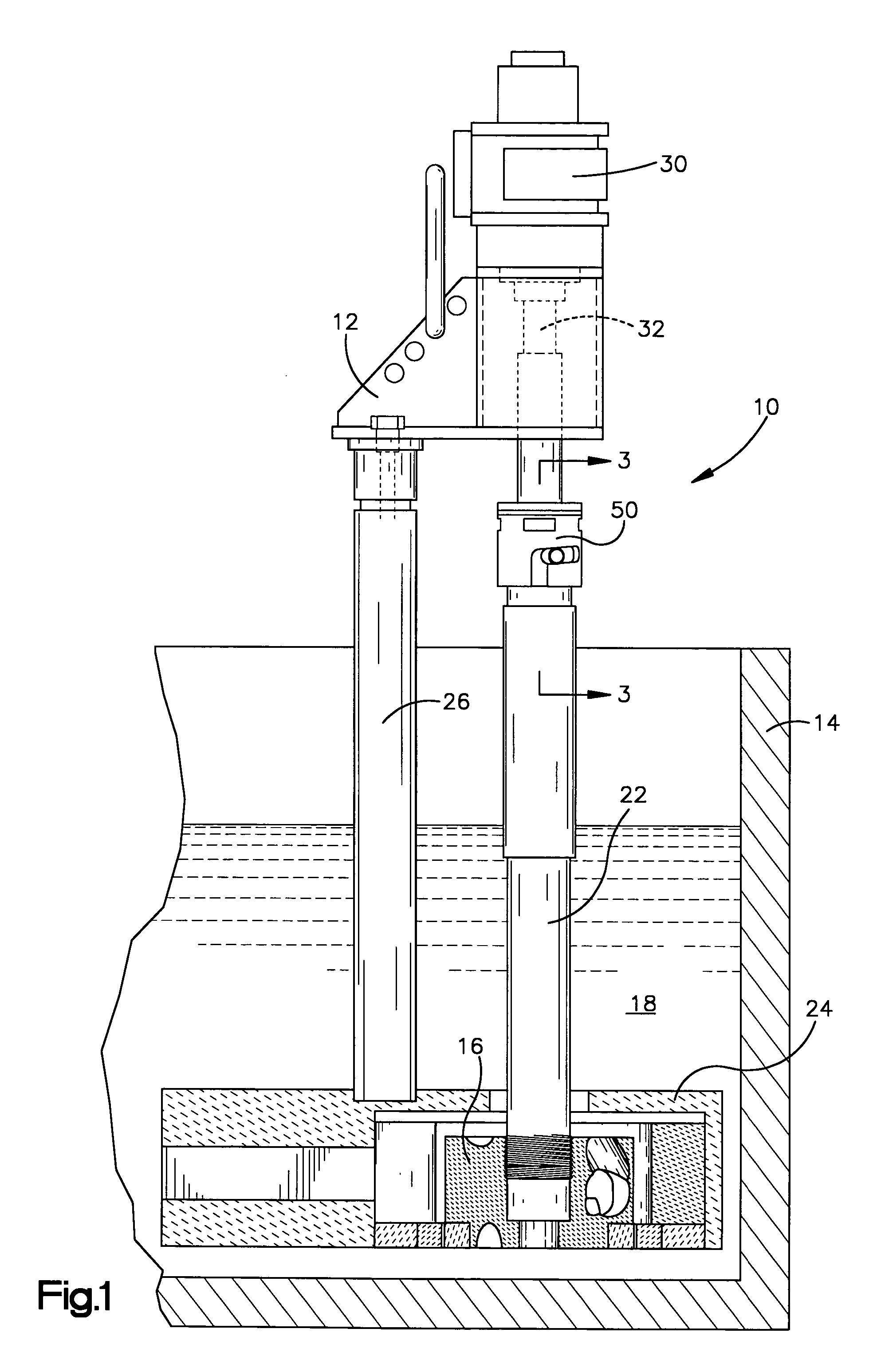
[0032] Referring to FIG. 1, an apparatus 10 for pumping molten metal embodying the present invention is illustrated. The apparatus 10 is mounted to a support fixture 12 disposed within a molten metal containment structure or vessel 14. The pump apparatus 10 includes at least one rotatable impeller 16 which in operation draws molten metal from a molten metal bath 18 and pumps the molten metal through a conduit 20 to a subsequent processing station or furnace (not shown). It should be understood that the apparatus of the present invention is not limited to the pump shown in the drawings, but rather is applicable to any motor shaft / impeller shaft coupling in a pump for pumping molten metal.

[0033] The pump apparatus 10 illustrated includes a gas injection shaft as best shown in FIG. 3. Gas is injected into the molten metal to react with impurities within the molten metal bath. Types of gas conventionally used include nitrogen, argon, and chlorine, among others. The specific gas selecte...


PUM


Abstract

A shaft coupling apparatus used in a pump assembly for pumping molten metal. The apparatus includes an impeller shaft, a drive shaft, and first and second coupling members. The first member engages the impeller shaft and includes a tube and two diametrically opposed pins. The second member includes a sleeve having an inner diameter adequate to receive the tube, a plate fixed to the sleeve having a mating surface cooperatively aligned with a mating surface of the impeller shaft, structure defining pin receiving slots, each slot adapted for guiding a pin into a retained position extending through the slot, and structure defining a plurality of voids in a sleeve outer surface. The pins and voids are rotatably engagable by a tool set such that the impeller and motor shafts are connectable and disconnectable by manual operation of the tool set. The apparatus may form a quick disconnect / connect gas injection shaft.

Description

FIELD OF THE INVENTION [0001] This invention relates to a shaft coupling used in pump assembly and, in particular, to a quick disconnect / connect gas injection shaft. BACKGROUND OF THE INVENTION [0002] Pumps used for pumping molten metal typically include a motor carried by a motor mount, a shaft connected to the motor at one end, and an impeller connected to the other end of the shaft. Such pumps may also include a base with an impeller chamber, the impeller being rotatable in the impeller chamber. Support members extend between the motor mount and the base and may include a shaft sleeve surrounding the shaft, support posts, and a tubular riser. An optional volute member may be employed in the impeller chamber. [0003] Pumps of this type are designed with shaft bearings, impeller bearings and with bearings in the base that surround these bearings to avoid damage of the shaft and impeller due to contact with the shaft sleeve or base. The shaft, impeller, and support members for such p...

Claims


Application Information

Patent Timeline
Patent Type & Authority Applications(United States)
IPC IPC(8): F16L37/248
CPCF16L37/248
Inventor THUT, BRUNO H.
Owner THUT BRUNO H
Why Eureka
Try Eureka