Battery charging device for a mobile apparatus using an ear-microphone jack

a mobile device and charging device technology, applied in the field of charging of mobile devices, can solve the problems of increasing the cost of manufacturing the phone and inconvenient carrying of the mobile phone, and achieve the effect of low cost and convenient carrying

Inactive Publication Date: 2005-04-14
SAMSUNG ELECTRONICS CO LTD
View PDF7 Cites 112 Cited by
  • Summary
  • Abstract
  • Description
  • Claims
  • Application Information

AI Technical Summary

Benefits of technology

[0012] It is, therefore, an object of the present invention to provide a small charging device for a mobile apparatus, which is easy to carry and low in cost.
[0014] In accordance with one aspect of the present invention, there is provided a battery charging device for a mobile apparatus. The device comprises a battery; an ear-microphone socket having a microphone contact, an earphone contact, and a common ground contact; a modem chip having a microphone input port connected to the microphone contact or an internal microphone and an earphone output port connected to the earphone contact or an internal speaker, the modem chip being driven by a voltage provided from the battery; and a cutting-off element connected between a power supply contact, which is any one of the microphone contact and the earphone contact, and the battery, for providing a charging voltage provided via the power supply contact to the battery and preventing a current from flowing backward from the battery to the modem chip.

Problems solved by technology

However, because a storage capacity of a battery is limited, there is a demand for a charging device for periodically charging the battery.
This charging method is disadvantageous in that different cradles are used according to the model and manufacturer of the mobile phone.
However, the charging devices illustrated in FIGS. 2A through 2D are also disadvantageous in that they are large in size, making it inconvenient to carry the mobile phone and increase the cost of manufacturing the phone.

Method used


Image

  • Battery charging device for a mobile apparatus using an ear-microphone jack
  • Battery charging device for a mobile apparatus using an ear-microphone jack
  • Battery charging device for a mobile apparatus using an ear-microphone jack

Examples


Embodiment Construction

[0024] Embodiments of the present invention will now be described in detail with reference to the accompanying drawings. In the following description, a detailed description of known functions and configurations incorporated herein has been omitted for conciseness.

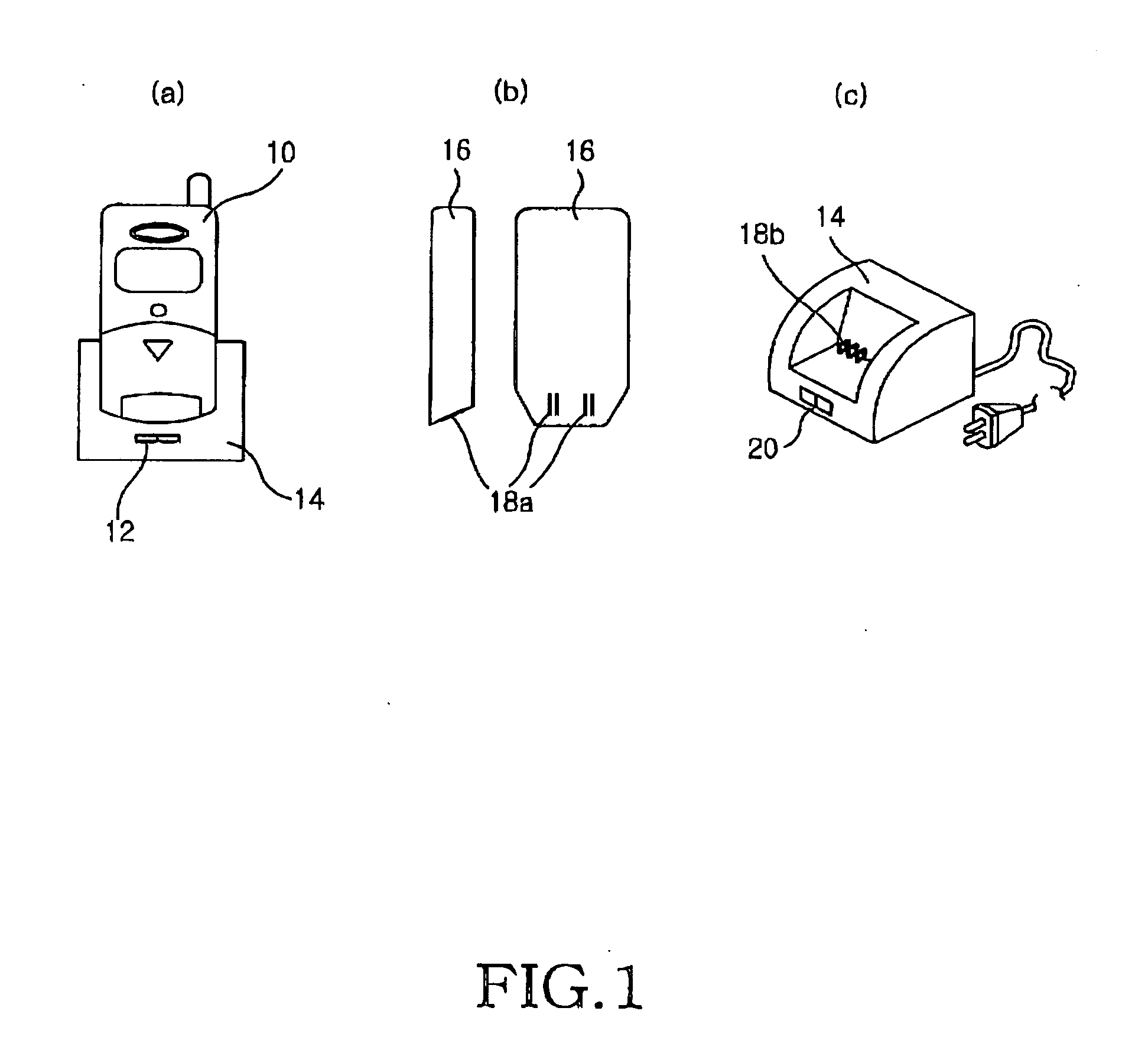
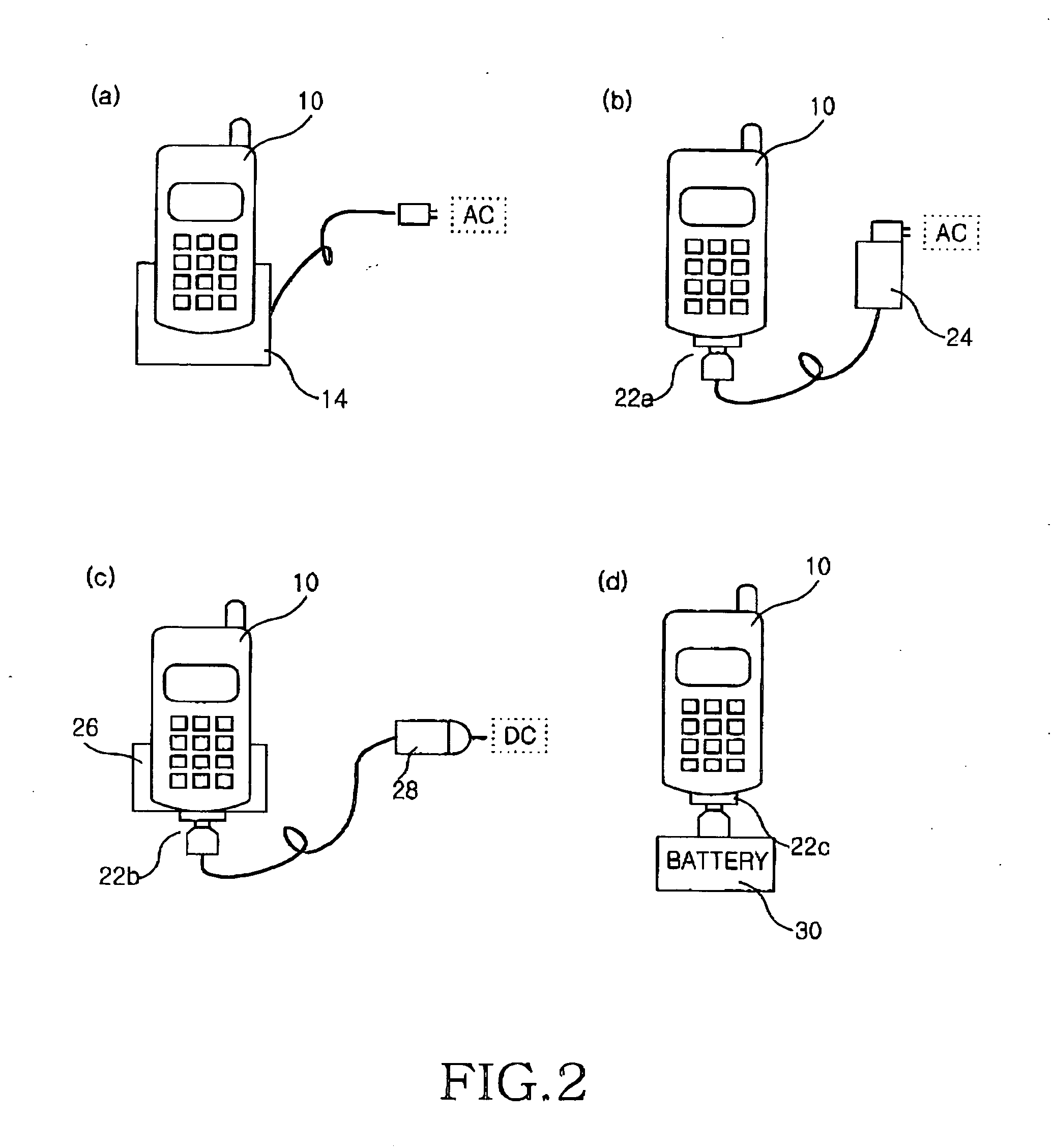
[0025] The present invention provides a charging device having a plug connectable to an earphone-microphone jack (hereinafter referred to as an “ear-microphone jack”) in order to charge a mobile apparatus including the ear-microphone jack. Herein, a description of an embodiment of the present invention will be made with reference to a mobile phone, for example, a conventional mobile apparatus having an ear-microphone jack.

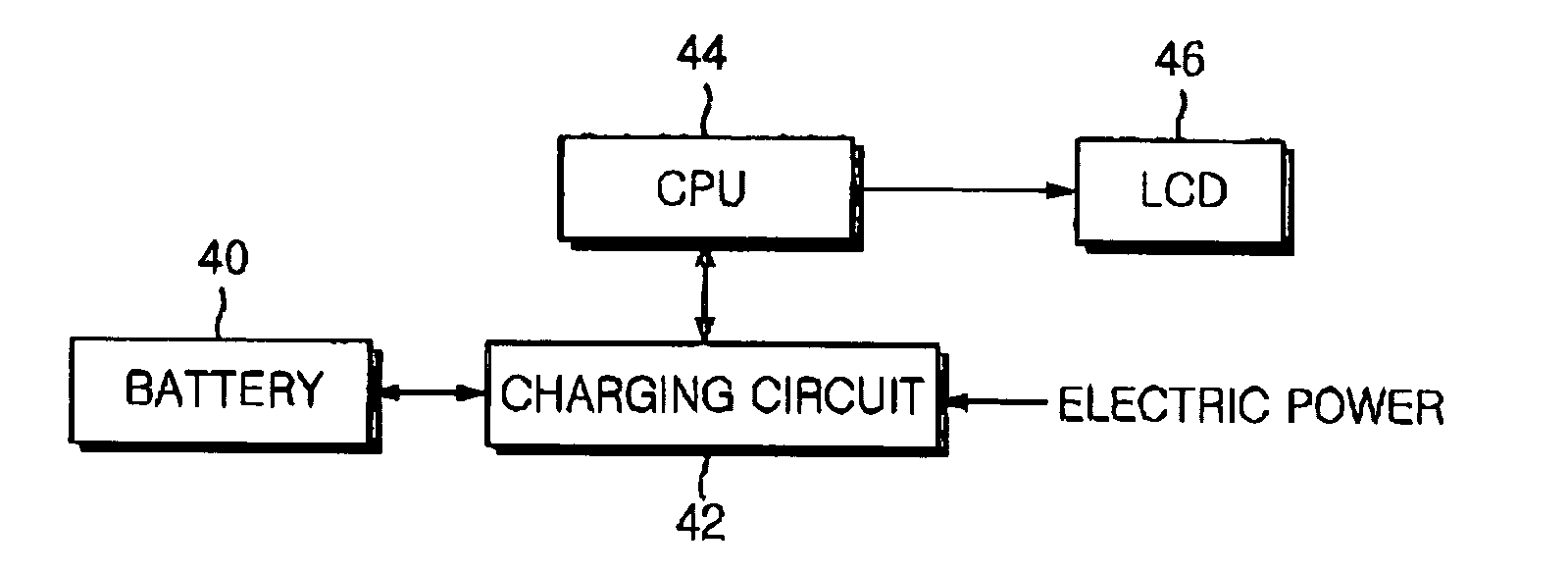
[0026]FIG. 3 is a block diagram illustrating an internal structure of a mobile phone employing a charging method according to an embodiment of the present invention. As illustrated, the mobile phone includes a battery 40 for powering circuits, a charging circuit 42 for charging the battery 40, and a cen...


PUM


Abstract

A battery charging device using an ear-microphone jack of a mobile apparatus. The battery charging device comprises a battery; an ear-microphone socket having a microphone contact, an earphone contact, and a common ground contact; a modem chip having a microphone input port connected to the microphone contact or an internal microphone and an earphone output port connected to the earphone contact or an internal speaker; and a cutting-off element connected between a power supply contact and the battery, for providing a charging voltage provided via the power supply contact to the battery and preventing a current from flowing backward from the battery to the modem chip. A power supply device comprises a plug having terminals connectable to contacts of the ear-microphone socket; and a power source connector for connecting a power supply source to the plug.

Description

[0001] This application claims the benefit under 35 U.S.C. § 119(a) of an application entitled “Battery Charging Device for Mobile Apparatus Using Ear-Microphone Jack” filed in the Korean Intellectual Property Office on Aug. 7, 2003 and assigned Serial No. 2003-54679, the entire contents of which are incorporated herein by reference.BACKGROUND OF THE INVENTION [0002] 1. Field of the Invention [0003] The present invention relates generally to the charging of a mobile apparatus. In particular, the present invention relates to a battery charging device using an ear-microphone jack of a mobile apparatus. [0004] 2. Description of the Related Art [0005] Mobile communication has become a necessity of present-day life. Accordingly, there is an increase in demand for a mobile apparatus having a call function and various additional functionalities, such as a cellular phone, a Personal Communications Service (PCS) phone, an International Mobile Telecommunication-2000 (IMT-2000) phone, Personal...

Claims


Application Information

Patent Timeline
Patent Type & Authority Applications(United States)
IPC IPC(8): H02J7/00H04M1/00
CPCH02J7/0054H02J2007/006H02J7/0055H02J7/0044H02J2207/30H02J2207/40H02J7/342H02J2310/22H02J7/00
Inventor HA, MIN-WOONGKIM, IN-KI
Owner SAMSUNG ELECTRONICS CO LTD
Why Eureka
Try Eureka