Magnetic assembly for magnetically actuated control devices

a magnetic assembly and control device technology, applied in the direction of magnetic/electric field switches, electrical devices, contacts, etc., can solve the problems of false alarm, inability to set the alarm, false alarm generation,

Active Publication Date: 2005-04-14
EDMONSON JR MAHLON WILLIAM
View PDF11 Cites 18 Cited by
  • Summary
  • Abstract
  • Description
  • Claims
  • Application Information

AI Technical Summary

Benefits of technology

[0024] A magnetically actuated apparatus for use with magnetically controlled devices is provided. The apparatus is mountable to a movable closure member, having a fixed support member and a movable support member that are displaceable relative to one another. The apparatus comprises a sensor that is mounted to the fixed support member and a magnetic actuator mountable to the movable member. The sensor has a pair of contact members that are connectable to an electronic circuit. The contact members form a switch that is actuated by the magnetic actuator. The magnetic actuator preferably comprises a plurality of aligned, alike biasing magnets. The magnets have like magnetic poles that combine to form an effective magnetic actuation field that has a given magnitude and a given direction that is greater than the magnitude and direction of any one of the magnets. As an alternate embodiment, the magnetic actuator comprises an elongated magnetic bar that has unique specific polarization that may be used to actuate the sensor. In operation, the effective magnetic actuation field of the magnetic actuator increases the distance in which the movable member is displaceable relative to the fixed member without a change in the electric condition of the sensor.

Problems solved by technology

What is illustrated here is that slight movement to a magnet that is perpendicular to a reed switch can cause a false alarm.
Once in the open state, the alarm cannot be set or if the alarm is on will trigger a false alarm.
This faulted condition results in the inability to set the alarm.
If the alarm system was on prior to the shift, then a false alarm would be generated.
If there wasn't any play then the window or door would be difficult to unlock.
Another problem associated with the current art gap distance the weather seals.
However, during warm weather months, the window cannot be opened far enough to vent air when the alarm is set because the magnet assembly 74 must remain within gap 79.
In climates in which an air conditioner is not desired to be used and fresh air is desired, present standard gaps and break distances provide very little, if any, flexibility to vent a room.
Adding to the problem with using standard industry gaps and break distances is the fact that irregularities are often present in window and door assemblies through wear and tear.
Also adding to the problem are foreign materials, such as paint, dust, dirt, and other objects that impede the ability of a window or door being closed all the way.
Failure to comply with such established gap and break distances in mounting proximity devices, such as 72, fails to provide acceptable tolerances for accommodating standard clearances, expected irregularities and foreign objects, which result in misalignments, spaces between the frame and corresponding closure members, and an inability to completely insure assemble 74 stays aligned within gap 79.

Method used


Image

  • Magnetic assembly for magnetically actuated control devices
  • Magnetic assembly for magnetically actuated control devices
  • Magnetic assembly for magnetically actuated control devices

Examples


Embodiment Construction

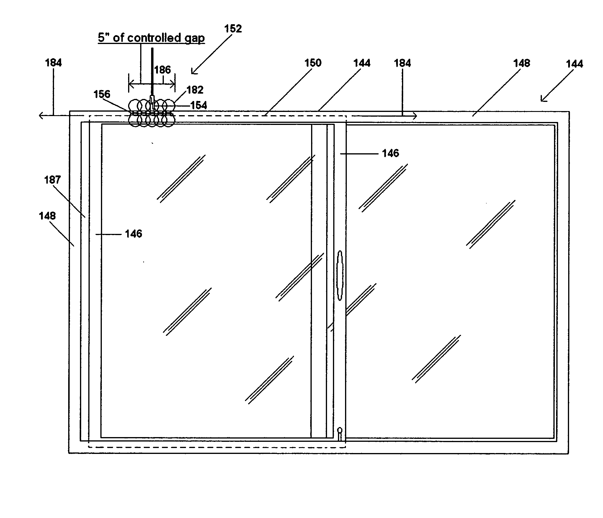
[0087]FIG. 9 shows a magnetically actuatable apparatus 84 of the present invention for use with magnetically or electrically controlled devices or systems such as, for example, magnetically actuated reed switches and proximity devices that are used with physical monitoring or alarm systems. Apparatus 84 includes an enhanced, actuating magnet assembly or magnetic actuator 86 and a magnetically actuatable control device or sensor 88, also referred to in the security industry as a contact, which are operatively connectable to or associated with one another. The magnet actuator 86 comprises an assembly of multiple or a plurality of aligned, alike biasing magnetic fields (two shown) having overlapping magnetic fields. The magnetic actuator 86 is provided to magnetically actuate or to put into use at least a portion of sensor 88 using magnetism or an electro-magnetic field. In a preferred embodiment, two magnets 90 and 92 are shown to create the aligned, alike magnetic fields. It should b...


PUM


Abstract

A magnetically actuated apparatus, which enlarges, extends and makes continuous magnetic fields used by magnetically controlled devices, such as a magnetic reed switch for use in physical security monitoring systems is shown. Apparatus includes a sensor and a magnetic actuator for use with a movable closure member. The sensor is mounted into to a fixed support member that is arranged for displacement relative to a second movable support member. The sensor has a pair of contacts that are connectable to an electronic circuit. The contacts form a switch that is actuated by the magnetic actuator. The magnetic actuator comprises a unique elongated magnet with specific polarity or a plurality of aligned, alike permanent magnets that are mountable to the second support member. The aligned magnets have like magnetic fields that align one another and combine to form an effective magnetic actuation field that has a given magnitude and a given direction that is greater that the magnitude and direction than any one of the magnets. The elongated magnet has a specific pole for a given distance as its controlling means. The effective magnetic actuation field increases the distance in which the movable support member is displaceable relative to the fixed support member without changing the electric condition of the sensor. The present invention creates a magnetic apparatus, having a wider and controllable gap and break point distance not found in the present art.

Description

REFERENCE TO PRIOR APPLICATION [0001] This application claims the benefit of U.S. Provisional Application No. 60 / 455,061, filed on Mar. 14, 2003, entitled “Magnetic Assembly For Magnetically Actuated Control Devises,” in the name of Mahlon William Edmonson, Jr.FIELD OF THE INVENTION [0002] The present invention relates to magnetically actuated control devices. In particular, the present invention relates to an enhanced magnetic assembly for use with magnetically actuatable controlled devices, such as a magnetic reed switch used in a physical security monitoring system. BACKGROUND OF THE INVENTION [0003] Physical monitoring systems are well known in the art. Conventional monitoring systems typically comprise a reed switch that is electrically connected by wires to an electronic circuit, such as alarm or machinery control system. The reed switch generally comprises a cylindrical glass capsule containing a pair of electrical contacts disposed therein. Each contact is attached to a flex...

Claims


Application Information

Patent Timeline
Patent Type & Authority Applications(United States)
IPC IPC(8): H01H9/00H01H36/00
CPCH01H36/0013
Inventor EDMONSON, MAHLON WILLIAM JR.
Owner EDMONSON JR MAHLON WILLIAM
Why Eureka
Try Eureka