Two-frequency Doppler distance measuring apparatus and detection system having the apparatus

a technology of detection system and measuring apparatus, which is applied in the direction of measuring devices, instruments, domestic applications, etc., to achieve the effect of high accuracy

Inactive Publication Date: 2005-04-14
ORMON CORP
View PDF17 Cites 23 Cited by
  • Summary
  • Abstract
  • Description
  • Claims
  • Application Information

AI Technical Summary

Benefits of technology

[0031] According to this invention, the distance of an object such as a human body having a complicated behavior and / or reflection surface can be measured and detected with high accuracy using the two-frequency Doppler method. In this way, the applications of the two-frequency Doppler distance measuring apparatus are widened.

Problems solved by technology

In the case where the behavior of a reflection object or the shape of the reflection surface is complicated, however, the Doppler signal contains various frequency components with a distorted waveform having a forked peak and a displacement of peak position.

Method used


Image

  • Two-frequency Doppler distance measuring apparatus and detection system having the apparatus
  • Two-frequency Doppler distance measuring apparatus and detection system having the apparatus
  • Two-frequency Doppler distance measuring apparatus and detection system having the apparatus

Examples


example 1

[0093] (Example 1 of Position Detection System)

[0094]FIG. 12 shows a position detection system using the two-frequency. Doppler distance measuring apparatus described above.

[0095] The position detection system 30 comprises a first two-frequency Doppler distance measuring apparatus 31, a second two-frequency Doppler distance measuring apparatus 32 and a position calculation unit 33. The two-frequency Doppler distance measuring apparatuses 31, 32 are arranged at an interval a with the antenna directivity thereof set in such a manner that the respective distance measurement areas intersect each other. The intersection of the distance measurement areas represents the detection area of the moving object.

[0096] When a moving object (intruder 34) enters the detection area, the two-frequency Doppler distance measuring apparatuses 31, 32 detect the Doppler signals and measure the distance to the intruder 34. These distance measurements are input to a position calculation unit 33.

[0097] Th...

example 2

[0102] (Example 2 of Position Detection System)

[0103]FIG. 13 shows a position detection system employing the two-frequency Doppler distance measuring apparatus described above.

[0104] The position detection system 40 comprises a scan antenna and scans the monitor area by sequentially switching the direction of beam radiation. The two-frequency Doppler distance measuring apparatus measures the distance in each beam direction. When a moving object (intruder 41) enters the monitor area, the two-frequency Doppler distance measuring apparatus detects the Doppler signals thereby to measure the distance to the intruder 41. The position calculation unit of the position detection system 40 calculates the two-dimensional position of the intruder 41 based on the distance measurement and the direction of the radiated beam.

[0105] By repeating this position detect operation, the traffic line of the intruder 41 can be detected. This position detection system 40, like the position detection system...


PUM


Abstract

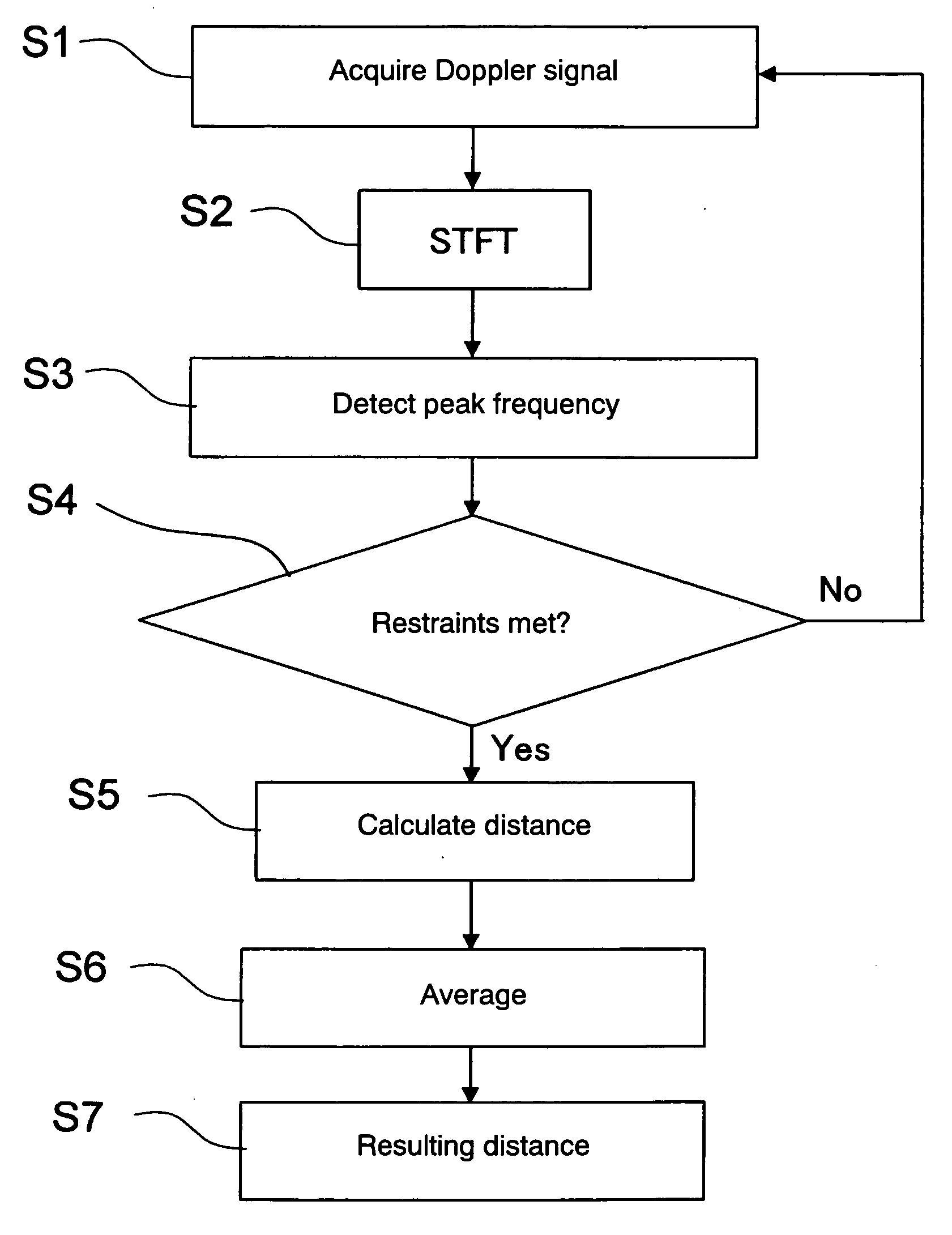
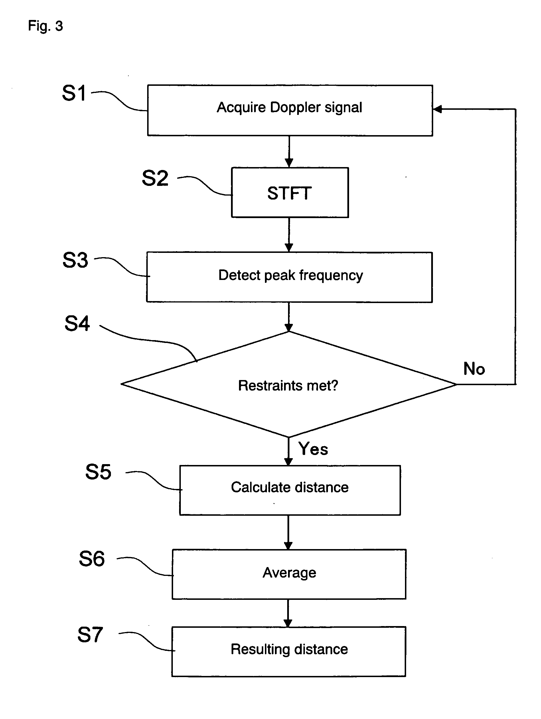
A technique is disclosed for accurate measurement of the distance and detection of an object such as a human body behaving in a complicated way and having a complicated reflection surface using the two-frequency Doppler method. Each of the two-frequency Doppler signals is subjected to the short time Fourier transform to produce a spectrum in a short time window. Based on restraints, it is determined whether the waveforms of the two spectra are analogous to each other or not, and only in the case where the waveforms are analogous, the Doppler signals of the particular time window are used for distance calculation. As a result, the Doppler signals having the phase information low in reliability are eliminated, and therefore high-accuracy distance measurement and object detection are possible.

Description

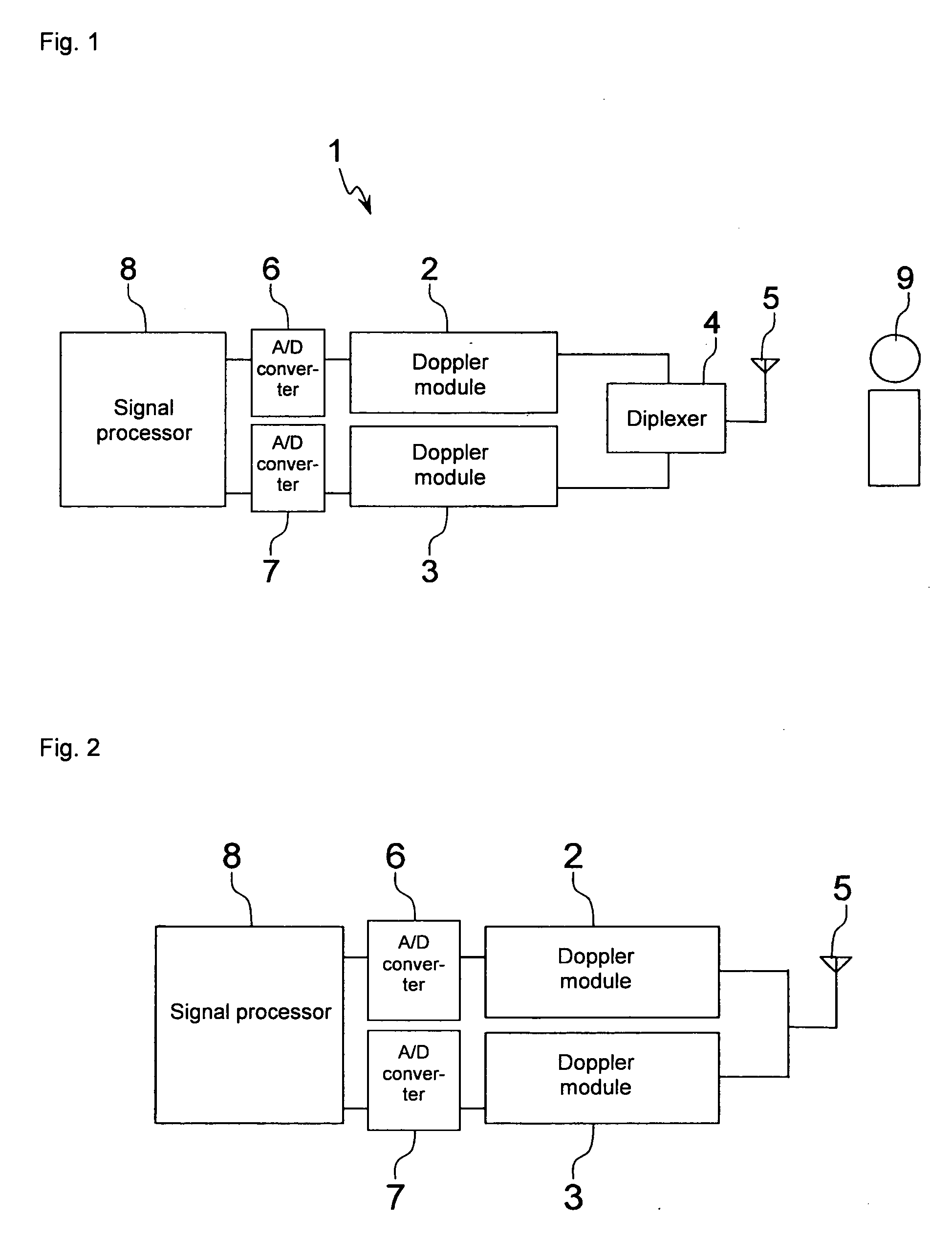
BACKGROUND OF THE INVENTION [0001] 1. Field of the Invention [0002] The present invention relates to a technique for measuring the distance to a reflection object using a two-frequency Doppler signal. [0003] 2. Description of the Related Art [0004] The Doppler effect is a phenomenon in which when a wave source and a reflection object move relatively to each other, the frequencies of the wave transmitted from the wave source and the wave reflected on the object undergo change. In the case where the wave source and the object approach each other, the frequency is increased, and vice versa. An apparatus utilizing this phenomenon is a Doppler sensor which is used to detect the presence or absence of a moving object and detect the moving speed of the object. [0005] The two-frequency Doppler sensor (two-frequency Doppler distance measuring apparatus) includes double Doppler modules for Doppler measurement. The modules each generate a Doppler signal individually using the continuous wave o...

Claims


Application Information

Patent Timeline
Patent Type & Authority Applications(United States)
IPC IPC(8): A47K4/00G01S13/50G01S13/52G01S13/56G01S13/58
CPCG01S13/584G01S13/52
Inventor OKAMURA, SHINICHIROKAWAI, TAKEHIROSAITO, KEISUKE
Owner ORMON CORP
Why Eureka
Try Eureka