
Sensor

a technology of sensors and sensors, applied in the field of sensors, can solve problems such as unsatisfactory changes in products, and achieve the effect of facilitating the migration of indicators

Inactive Publication Date: 2005-04-14
ANDERSEN ALF
View PDF5 Cites 27 Cited by
  • Summary
  • Abstract
  • Description
  • Claims
  • Application Information

AI Technical Summary

Benefits of technology

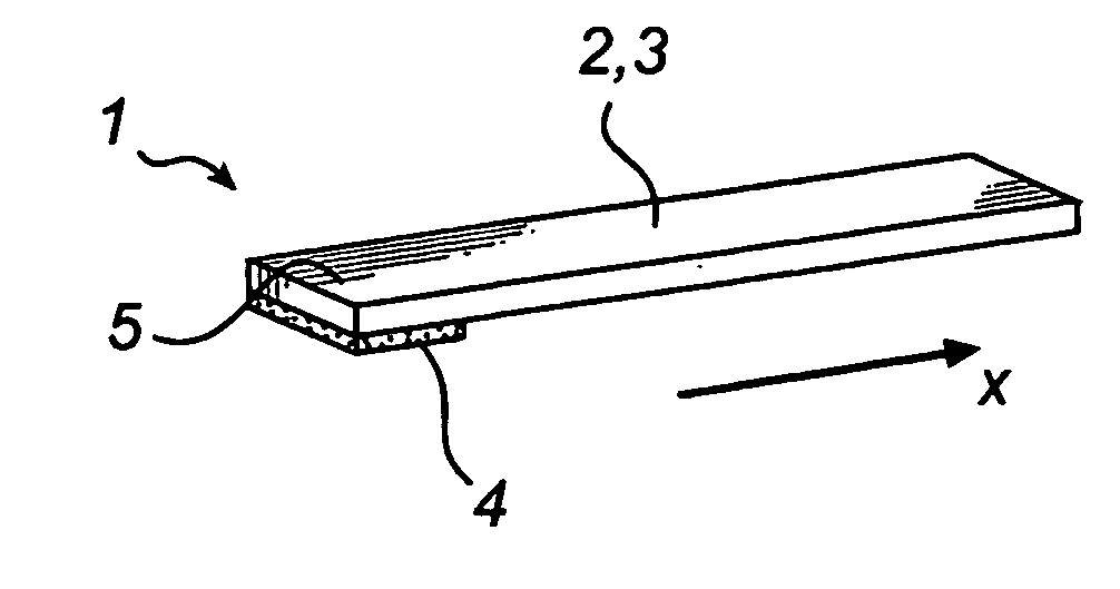
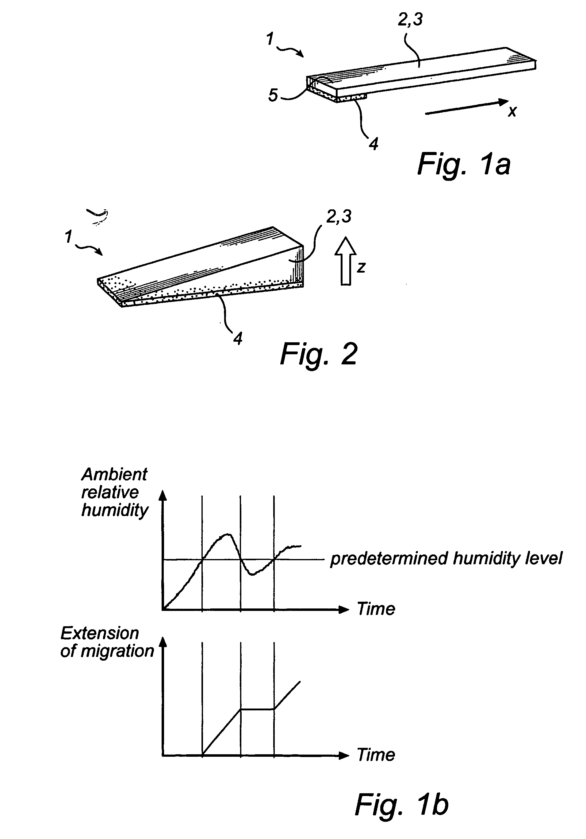
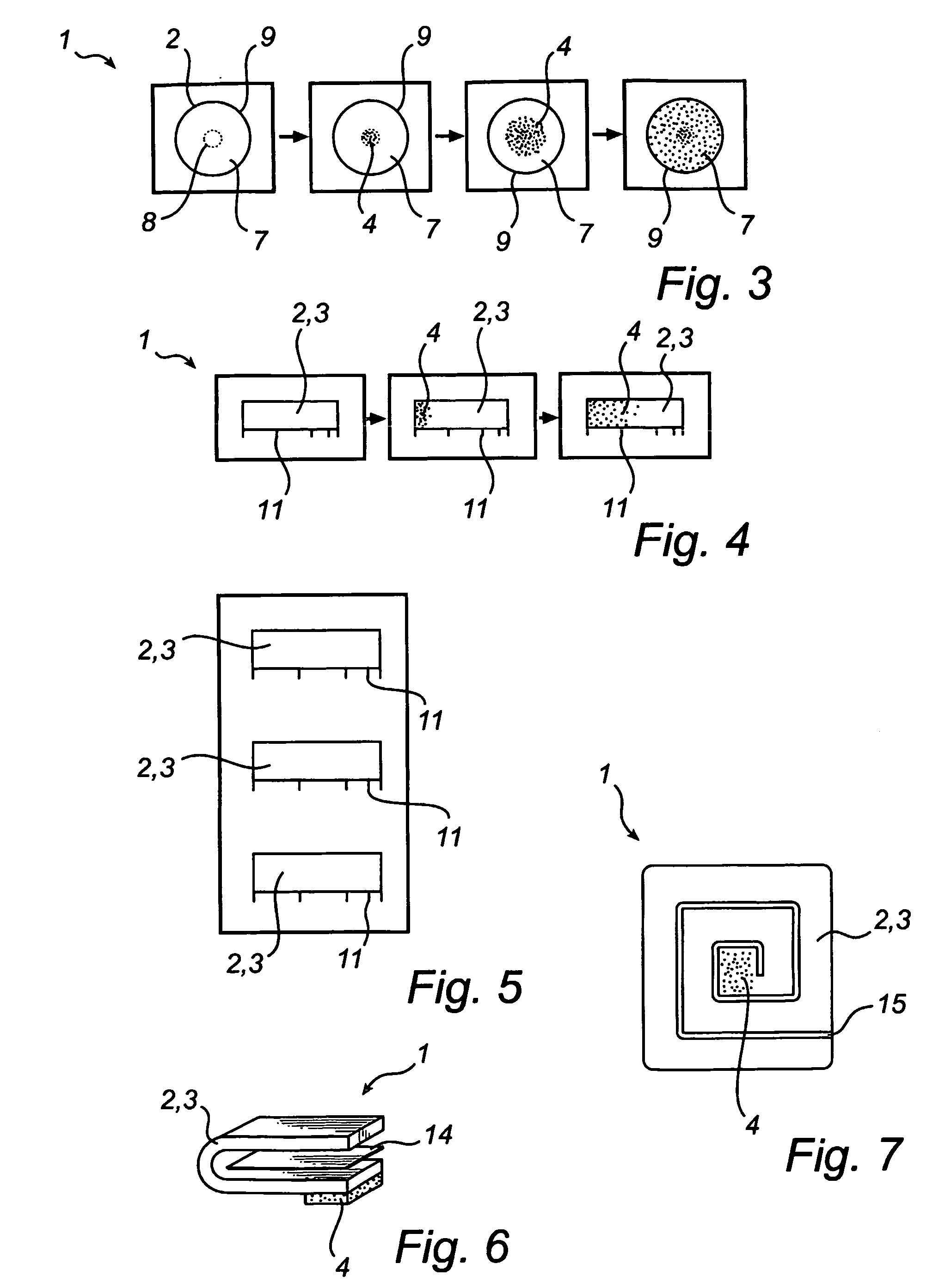
[0009] According to a first aspect of the invention, the above and other objects are achieved with a sensor for indicating a cumulative time period of presence of an ambient relative humidity there the sensor comprises an indicator and a carrier. The indicator is located at one or more limited portions of the carrier. The carrier allows migration of the indicator within the carrier and the indicator causes an extension thereof by migrating from the one or more limited portions, when the ambient relative humidity level exceeds a predetermined level. Further, the extension by migration is detectable by a user and the cumulative time period is related to the extension by migration and the characteristics of the indicator and the carrier. This means that the carrier allows the indicator to migrate within and / or at a surface layer of the carrier when a predetermined humidity level is exceeded and ceases migration of the indicator when the ambient relative humidity level is lowered below said predetermined level and resuming migration when the ambient relative humidity level again exceeds said predetermined level. An advantage of using a sensor according to the invention compared to a sensor with a so called wick action using capillary rising is that it is possible to indicate a cumulative time period of presence of an ambient relative humidity.
[0048] In a preferred embodiment of the invention the sensor is at least one of a sensitive items humidity sensor, a food stuff humidity sensor, a building- or construction material humidity sensor, a pharmaceutical humidity sensor, an electronic equipment humidity incorporating at least one of the characteristics of the sensor described above and prepared according to at least one of the previously mentioned processes. One large advantage with the sensor according to the present invention is that the sensor may be used in a very wide range of different business areas. The sensor is easily used everywhere where there is a risk that a certain item is exposed to moisture. For instance, it is of interest to indicate the amount of moisture in boats, vehicles, buildings and / or houses. Also, military materials, such as weapons, are sensitive to moisture.

Problems solved by technology

Exposure to moisture can lead to undesired changes to a product during manufacture, storage, handling or transportation.
However, the humidity level measured is the level inside hollow goods using a complicated device shown in the document.
A disadvantage with the sensors in the prior art is that they preferably indicate the exposure as such for predetermined levels of relative humidity.

Method used


Image

  • Sensor
  • Sensor
  • Sensor

Examples


example 1

[0075] Preparation of Sensors

[0076] A glass fibre filter of the type MGA (Munktell) was used as carrier. The salt KCl (85% RH, quality p.a.) was used as absorbent component and quinoline yellow (BI04), caramine (E120) and patent blue (B131) (food quality) respectively, were used as indicator dyes. The deionised water used exhibited a quality of 18 M ohm / cm.

[0077] The carriers have been prepared in two different ways with the same results, either by dipping the carrier into a concentrated salt solution (KCl) or by spraying a salt solution on one side of the carrier. In this case the other side of the carrier was vented. The doped carrier is then dried to a stable weight. The indicator dye, which is dispersed in isopropanole, is applied on one side of the dried and doped carrier. The sensor is then placed in a climate chamber having a relative humidity (RH) level lower than 55% RH.

[0078] Treatment of Sensors in a Climate Chamber

[0079] The test samples of the different sensors had ...


PUM

PropertyMeasurementUnit
RHaaaaaaaaaa
RHaaaaaaaaaa
relative humidityaaaaaaaaaa

Abstract

The present invention relates to sensor for indicating a cumulative time period of presence of an ambient relative humidity, there the sensor comprising an indicator and a carrier and the indicator being located at one or more limited portions of the carrier. The carrier allowing migrating of the indicator within the carrier and the indicator causing an extension thereof by migrating from the one or more limited portions when the ambient relative humidity level exceeds a predetermined level. Further, the extension by migrating being detectable by a user and the cumulative time period being related to the extension by migrating and the characteristics of the indicator and the carrier. The present invention also relates to a method for reading the cumulative time period of presence of an ambient relative humidity indicated by a sensor and a method for providing a sensor for indicating a cumulative time period of presence of an ambient relative humidity by providing a carrier with an indicator.

Description

TECHNICAL FIELD OF THE INVENTION [0001] This invention relates to a sensor for indicating a cumulative time period of presence of an ambient relative humidity. The present invention also relates to a method for reading a cumulative time period of presence of an ambient relative humidity indicated by a sensor and a method for providing a sensor for indicating a cumulative time period of presence of an ambient relative humidity by providing a carrier with an indicator, wherein the indicator is arranged at one or more limited portions of the carrier. BACKGROUND OF THE INVENTION [0002] Exposure to moisture can lead to undesired changes to a product during manufacture, storage, handling or transportation. Examples of moisture sensitive goods may be construction materials, food stuff, pharmaceuticals, boats, buildings, houses, vehicles, electronic equipment and so on. There are some known sensors in the prior art for indicating moisture. [0003] U.S. Pat. No. 4,292,916 describes a timer an...

Claims


Application Information

Patent Timeline
Patent Type & Authority Applications(United States)
IPC IPC(8): G01N31/22
CPCG01N21/80G01N21/81G01N2021/7723G01N31/229G01N31/222
Inventor ANDERSEN, ALF
Owner ANDERSEN ALF
Learn More