
Method of recording information, equipment thereof and information recording medium

a technology of information recording and information recording medium, applied in the field of information recording medium, a method of recording information, can solve the problems of difficult stable recording, complicated bca producing equipment, damaged recording layer during processing, etc., and achieve the effect of high wavelength dependence, easy and stable formation

Active Publication Date: 2005-04-14
PANASONIC CORP
View PDF11 Cites 9 Cited by
  • Summary
  • Abstract
  • Description
  • Claims
  • Application Information

AI Technical Summary

Benefits of technology

[0011] An object of the present invention is to solve the conventional problems, and to provide a method for easily and stably recording identification data of a medium, even when using the write-once recording medium or having a recording material with a high wavelength dependency, as well as equipment thereof and an optical disk having a BCA pattern thereon.
[0015] From this structure, because the recording on the information recording layer is performed indirectly through the light absorption layer, the identification data is stably recorded by reducing the deformation of the information recording layer caused by heat.
[0017] From this structure, preparing a new light absorption layer is not necessary, and the identification data can be recorded at high quality and low cost.
[0019] From this structure, because mark broadening caused by heat propagation can be reduced, the identification data can be recorded at high quality.
[0024] From this structure, the identification data can be recorded at high quality by using the difference of a reflecting ratio between a crystalline state and a non-crystalline state. The information recording layer is composed of a write-once phase-changeable recording material, and the identification data is recorded by changing a non-crystalline phase of the information recording layer to a crystalline phase. In this situation, although the temperature of the information recording layer becomes high, because the recording on the information recording layer is indirectly performed through the light absorption layer, the identification data is stably recorded by reducing the deformation of the information recording layer caused by heat.
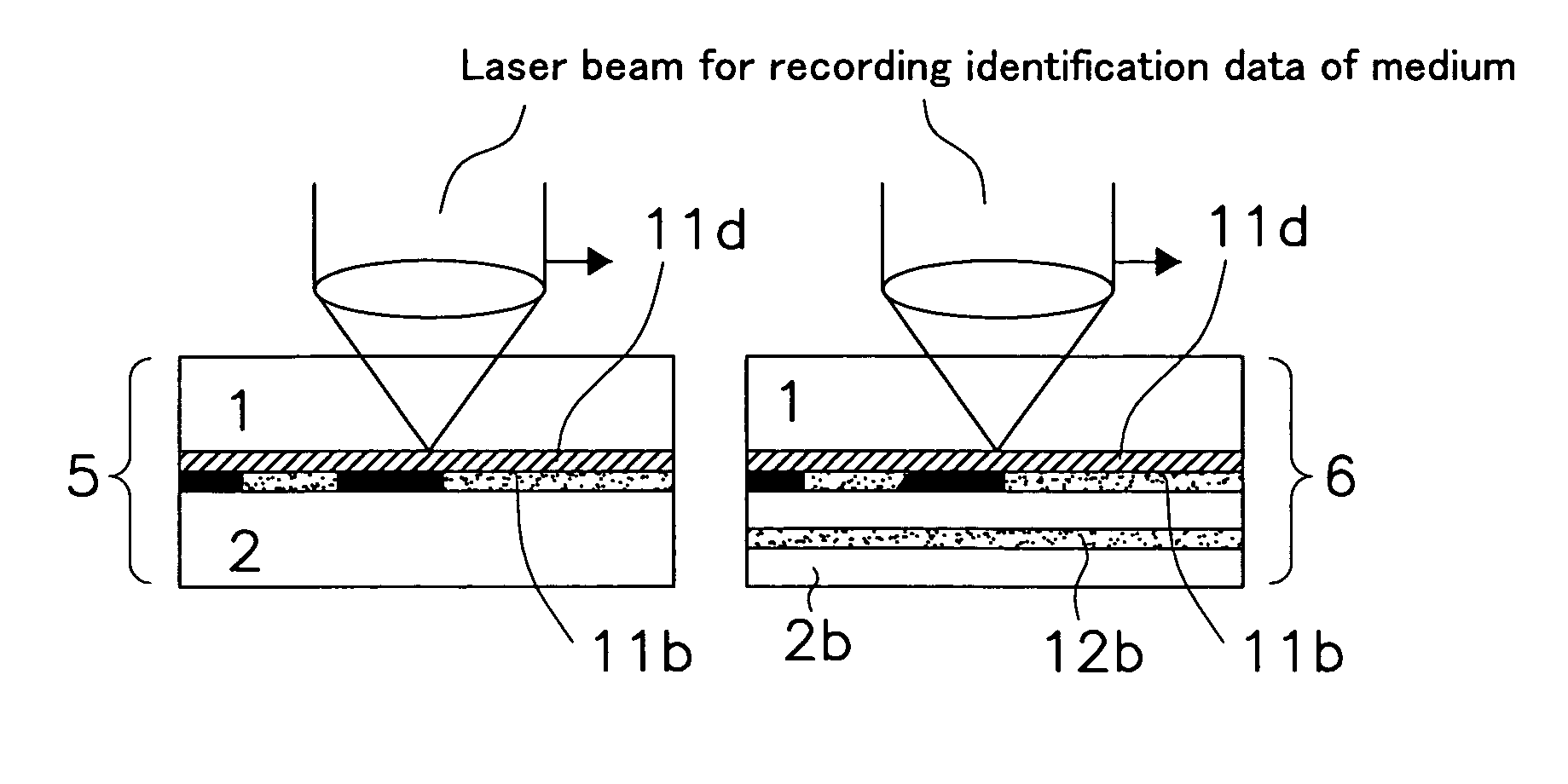
[0029] According to the method of recording information of the present invention, because identification data of a medium is recorded by applying a laser beam from a side opposite to where user data is recorded / reproduced, a BCA pattern can be formed easily and stably, regardless of whether using a single-layer or a multiple-layer optical disk and even when using recording materials which generally have a high wavelength dependency.

Problems solved by technology

This can complicate BCA producing equipment.
In addition, when using recording materials which generally have a high wavelength dependency such as organic dyes, because the recording conditions can vary due to even a slight change in recording wavelength or in optical properties of the dye material, stable recording has been a difficult task.
In this instance, because the medium has fairly low temperature in the recording mode, it is rare that the recording layer is damaged during the processing.
Thus, a hot section is produced over a significantly large area on the recording layer, and the recording layer is damaged.
This causes the problem of decreasing the signal quality when reproducing the BCA.

Method used


Image

  • Method of recording information, equipment thereof and information recording medium
  • Method of recording information, equipment thereof and information recording medium
  • Method of recording information, equipment thereof and information recording medium

Examples


embodiment

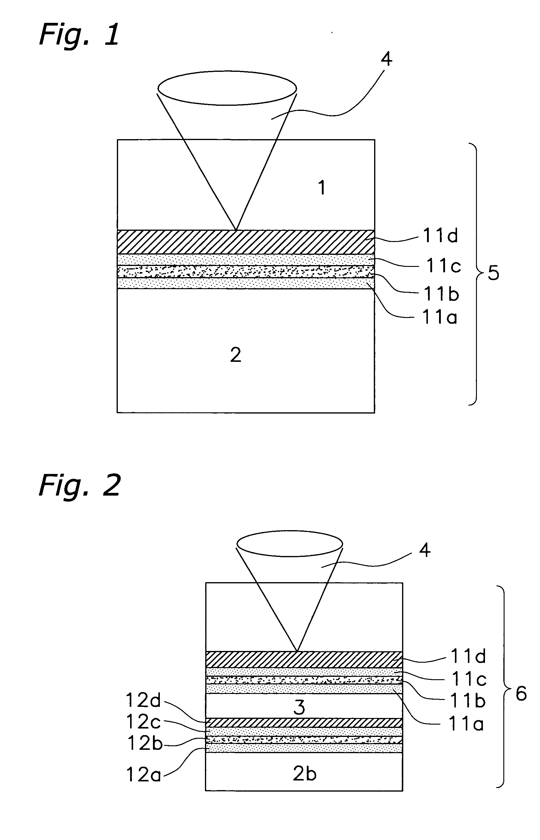
[0043]FIG. 1 is a cross-sectional diagram showing an optical disk 5 having a single information recording layer which is used in the method of recording information of the embodiment of the present invention.

[0044] In FIG. 1, reference numeral 11a is a front-side dielectric layer, reference numeral 11c is a back-side dielectric layer, reference numeral 11b is a recording layer, reference numeral 11d is a reflecting layer, reference numeral 1 is a substrate and reference numeral 2 is a cover layer. The single-layer optical disk 5 was formed by the following procedure. On the transparent substrate 1 made of a polycarbonate with 1.1 mm thickness and having a tracking groove, the reflecting layer 11d made of Al alloy with thickness 40 nm, a ZnS—SiO2 back-end dielectric layer 11c with thickness 30 nm, a Te—O—Pd recording layer 11b with thickness 20 nm and a ZnS—SiO2 front-side dielectric layer 11a with thickness 40 nm were formed in this order using a vacuum sputtering method. Then, the...


PUM

PropertyMeasurementUnit
thicknessaaaaaaaaaa
thicknessaaaaaaaaaa
thicknessaaaaaaaaaa

Abstract

Because conditions for recording identification data of a medium vary in accordance with the structure of different media, such as a single-layer or a multiple-layer structure, stable data recording has been a difficult task. To solve this problem, an incident side of the laser beam for recording identification data on a single-layer optical disk 5 and a double-layer optical disk 6 is the opposite side of a substrate 1 upon which user data is recorded. From this structure, even in a double-layer optical disk 6, the recording is not affected by the recording layer of a second layer 12b and the like. Therefore, in the double-layer optical disk 6, identification data of the medium can be recorded under the same conditions as the single-layer optical disk 5.

Description

BACKGROUND OF THE INVENTION [0001] 1. Field of the Invention [0002] The present invention relates to an information recording medium, a method of recording information thereon, and equipment thereof. [0003] 2. Description of the Prior Art [0004] Recently, due to increasing information recording capacity of an optical recording medium, increasing distribution of information which is recorded on an optical recording medium and improving protection techniques against illegal copies, a technique for recording identification data on all optical recording media is desired for security purposes. [0005] To service this demand, as recording identification data on an optical recording medium for example, the following technique is generally used: preparing a write-once type area (Burst Cutting Area, hereinafter referred to as a “BCA”) on which a barcode is overwritten on a pit of a read-only optical recording medium, and then during manufacturing of the optical recording medium, recording ide...

Claims


Application Information

Patent Timeline
Patent Type & Authority Applications(United States)
IPC IPC(8): G11B5/09G11B7/00G11B7/0045G11B7/007G11B7/2403G11B7/24038G11B7/24094G11B7/26G11B20/10
CPCG11B7/00454G11B7/00736G11B7/2403G11B2007/0013G11B7/24094G11B7/268G11B7/24038G11B7/0045
Inventor TAKAHASHI, KATSUYUKINISHIUCHI, KENICHIMIYAGAWA, NAOYASUNISHIHARA, TAKASHI
Owner PANASONIC CORP
Learn More