Safety mechanisms for belt cartridge used with chest compression devices

Inactive Publication Date: 2005-04-14
ZOLL CIRCULATION
View PDF3 Cites 14 Cited by
  • Summary
  • Abstract
  • Description
  • Claims
  • Application Information

AI Technical Summary

Benefits of technology

[0005] The devices and methods shown below provide for a belt cartridge for use in devices that perform chest compressions. The cartridge has a belt, a compression pad attached to the belt, a cover plate through which the belt is threaded, a belt spline for attaching the belt to a drive spool of a belt drive platform, and belt guards rotatably attached to the cover plate. During use, the cover plate and belt guards are removably attached to the housing of the belt drive platform. In turn, the belt extends out of the housing and is secured around the patient. The safety mechanisms include a breakable link, liner socks, belt guards and a rapid-release connector. The breakable link is attached near the transition section of the belt. The breakable link prevents an unsafe amount of tension from developing in the belt by breaking at a pre-selected load threshold.
[0006] The liner socks protect the patient from friction and contain the breakable link. The liner socks cover the belt so that the belt slides against the liner socks and not against the patient. If the link breaks, then the link remains inside a sock.
[0007] The belt guards protect foreign objects from entering the belt drive platform. Thus, articles of clothing, tools, fingers, other body parts, or other foreign objects are less likely to interfere with the belt drive platform. Similarly, the patient and rescuer are less likely to be injured by the device since the belt guards protect the moving parts of the belt drive platform.
[0008] The rapid-release connector allows the belt to be removed safely even during compressions. The rapid release connector is placed on the load distribution sections of the belt. The connector is a combination of hook and loop fasteners and a peg disposed within an eyelet.

Problems solved by technology

However, even experienced paramedics cannot maintain adequate chest compressions for more than a few minutes.
Thus, CPR is not often successful at sustaining or reviving the patient.

Method used


Image

  • Safety mechanisms for belt cartridge used with chest compression devices
  • Safety mechanisms for belt cartridge used with chest compression devices
  • Safety mechanisms for belt cartridge used with chest compression devices

Examples


Embodiment Construction

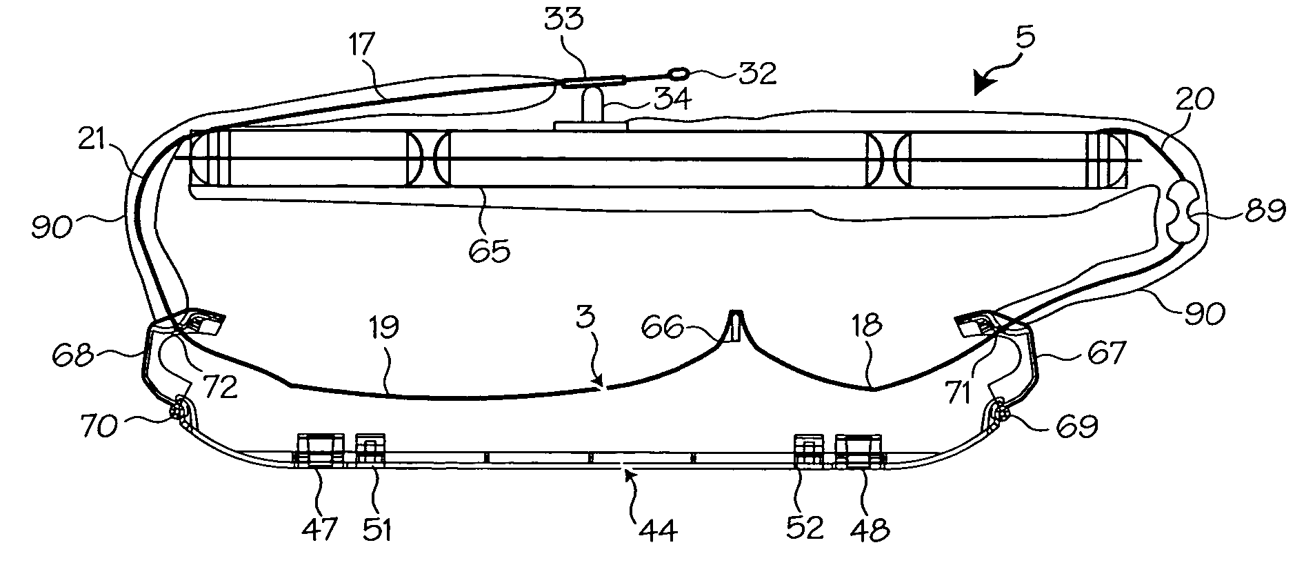
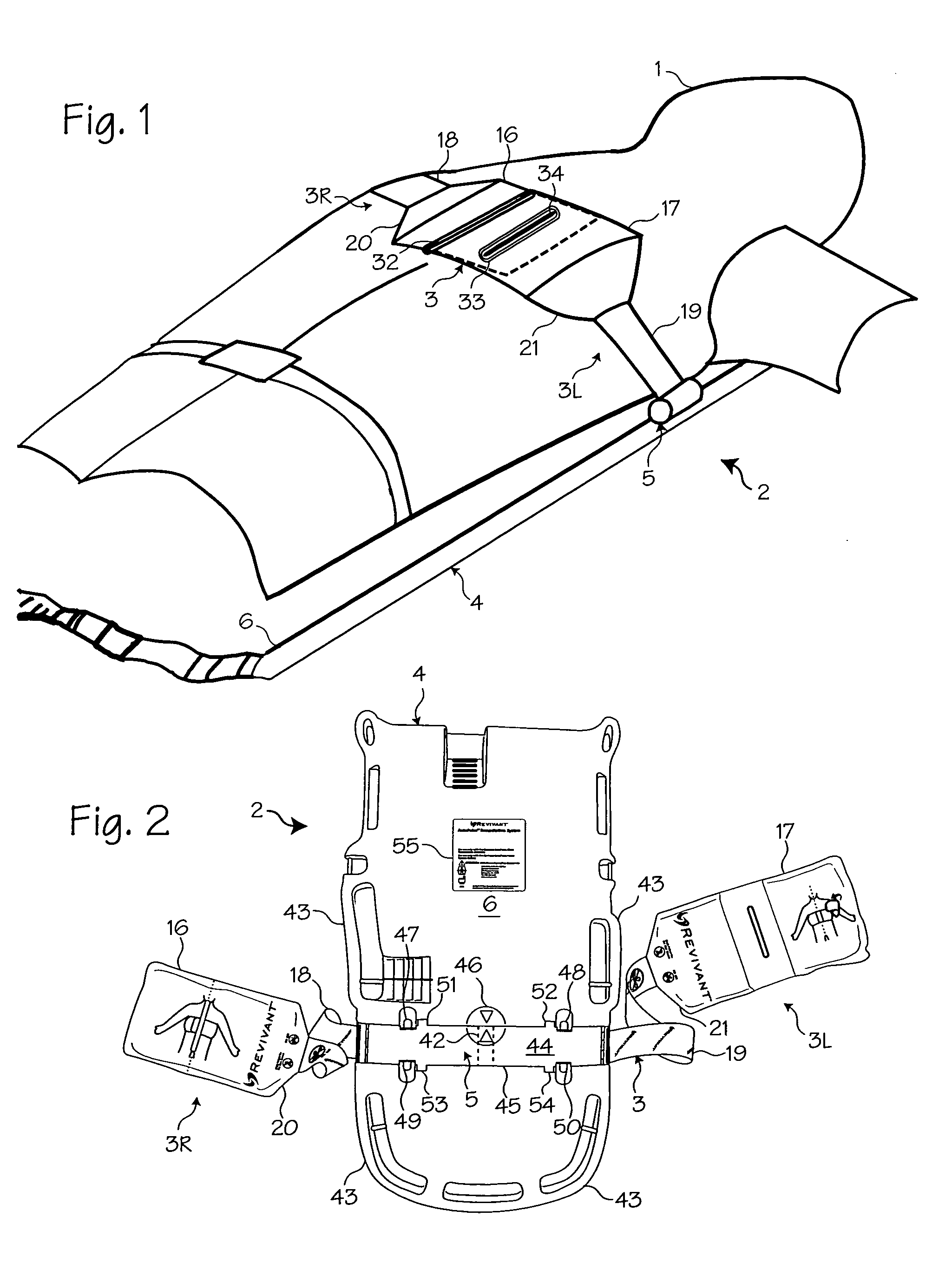
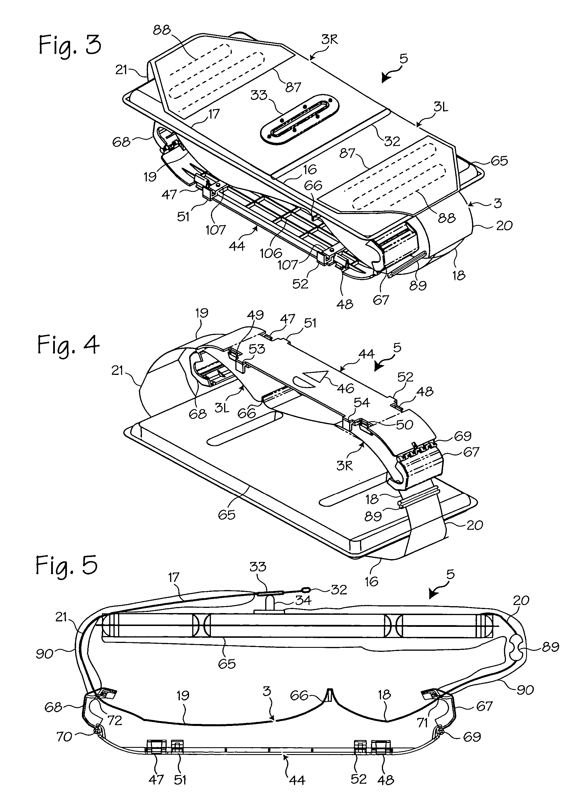
[0018]FIG. 1 shows the chest compression belt fitted on a patient 1. A chest compression device 2 applies compressions with the belt 3, which has a right belt portion 3R and a left belt portion 3L. The chest compression device 2 includes a belt drive platform 4 and a compression belt cartridge 5 (which includes the belt). The belt drive platform includes a housing 6 upon which the patient rests, a means for tightening the belt, a processor and a user interface disposed on the housing. The means for tightening the belt includes a motor, a drive train (clutch, brake and / or gear box) and a drive spool upon which the belt spools during use. Various other mechanisms may be used to tighten the belt, including the mechanisms shown in Lach et al., Resuscitation Method and Apparatus, U.S. Pat. No. 4,774,160 (Sep. 13, 1988) and in Kelly et al., Chest Compression Apparatus for Cardiac Arrest, U.S. Pat. No. 5,738,637 (Apr. 14, 1998). The entirety of these patents is hereby incorporated by refer...


PUM


Abstract

Safety mechanisms for compression belt cartridges used in chest compression devices. The safety mechanisms include a breakable link, liner socks, belt guards and a rapid-release connector. The breakable link ensures that unsafe belt tension will not occur. The liner socks protect the patient from friction and contain the breakable link. The belt guards protect foreign objects from entering the belt drive platform. The rapid-release connector allows the belt to be removed safely even during compressions.

Description

FIELD OF THE INVENTIONS [0001] The inventions described below relate to emergency medical devices and methods and the resuscitation of cardiac arrest patients. BACKGROUND OF THE INVENTIONS [0002] Cardiopulmonary resuscitation (CPR) is a well-known and valuable method of first aid used to resuscitate people who have suffered from cardiac arrest. CPR requires repetitive chest compressions to squeeze the heart and the thoracic cavity to pump blood through the body. Artificial respiration, such as mouth-to-mouth breathing or a bag mask apparatus, is used to supply air to the lungs. When a first aid provider performs manual chest compression effectively, blood flow in the body is about 25% to 30% of normal blood flow. However, even experienced paramedics cannot maintain adequate chest compressions for more than a few minutes. Hightower, et al., Decay In Quality Of Chest Compressions Over Time, 26 Ann. Emerg. Med. 300 (September 1995). Thus, CPR is not often successful at sustaining or re...

Claims


Application Information

Patent Timeline
IPC IPC(8): A61H31/00
CPCA61H31/005A61H31/006A61H31/008A61H31/00A61H2201/5007Y10S601/20Y10S601/06A61H2201/0173
Inventor KATZ, BOB H.DALBEC, TIMOTHY R.HALL, GREGORY W.
Owner ZOLL CIRCULATION
Why Eureka
Try Eureka