Anastomosis apparatus and methods of deployment and manufacture

a technology of anastomosis and equipment, applied in the field of anastomosis equipment and methods of deployment and manufacture, can solve the problems of requiring an exhaustive amount of time, affecting the healing effect of the patient, so as to achieve secure and reliable anastomosis, quick biocompatible bonding, and easy penetration of tissue.

Inactive Publication Date: 2005-04-14
WRIGHT DAVID WALTER
View PDF11 Cites 41 Cited by
  • Summary
  • Abstract
  • Description
  • Claims
  • Application Information

AI Technical Summary

Benefits of technology

[0010] Objects, features and advantages of this invention include an apparatus and method that provide a secure and reliable anastomosis between a tubular duct and a wall of a vessel, establish a quick biocompatible bond between mating tissues, impart a biasing force maintaining mating tissues in abutting contact with one another, readily penetrates tissue without damaging the tissue, provides a quick and reliable mechanism in which to attach separate tissues to one another, is of relatively simple design and is economical in manufacture, use and assembly.

Problems solved by technology

Though using sutures to join segments of tissue to one another in open heart surgery, or other forms of surgery, has proven successful, not only does it require an exhaustive amount of time in surgery, there is also a danger of the suture becoming damaged.
Damage to a portion of the suture may result in many ways, such as through inadvertent grasping or clamping by a surgical instrument.
Ordinarily, a damaged piece of suture has a substantially reduced tensile strength and thus may ultimately fail to maintain the pieces of tissue joined to one another.

Method used


Image

  • Anastomosis apparatus and methods of deployment and manufacture
  • Anastomosis apparatus and methods of deployment and manufacture
  • Anastomosis apparatus and methods of deployment and manufacture

Examples


Embodiment Construction

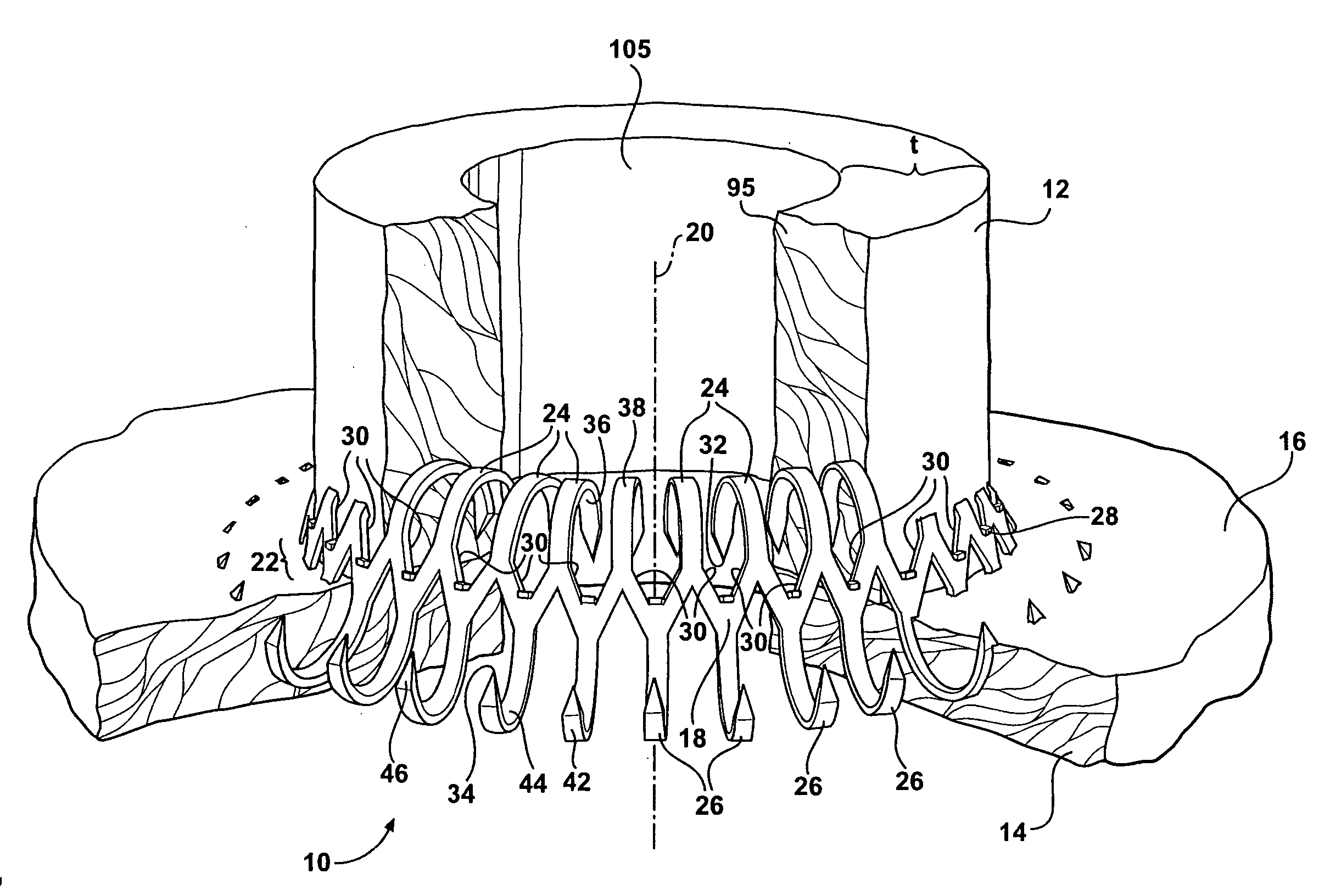
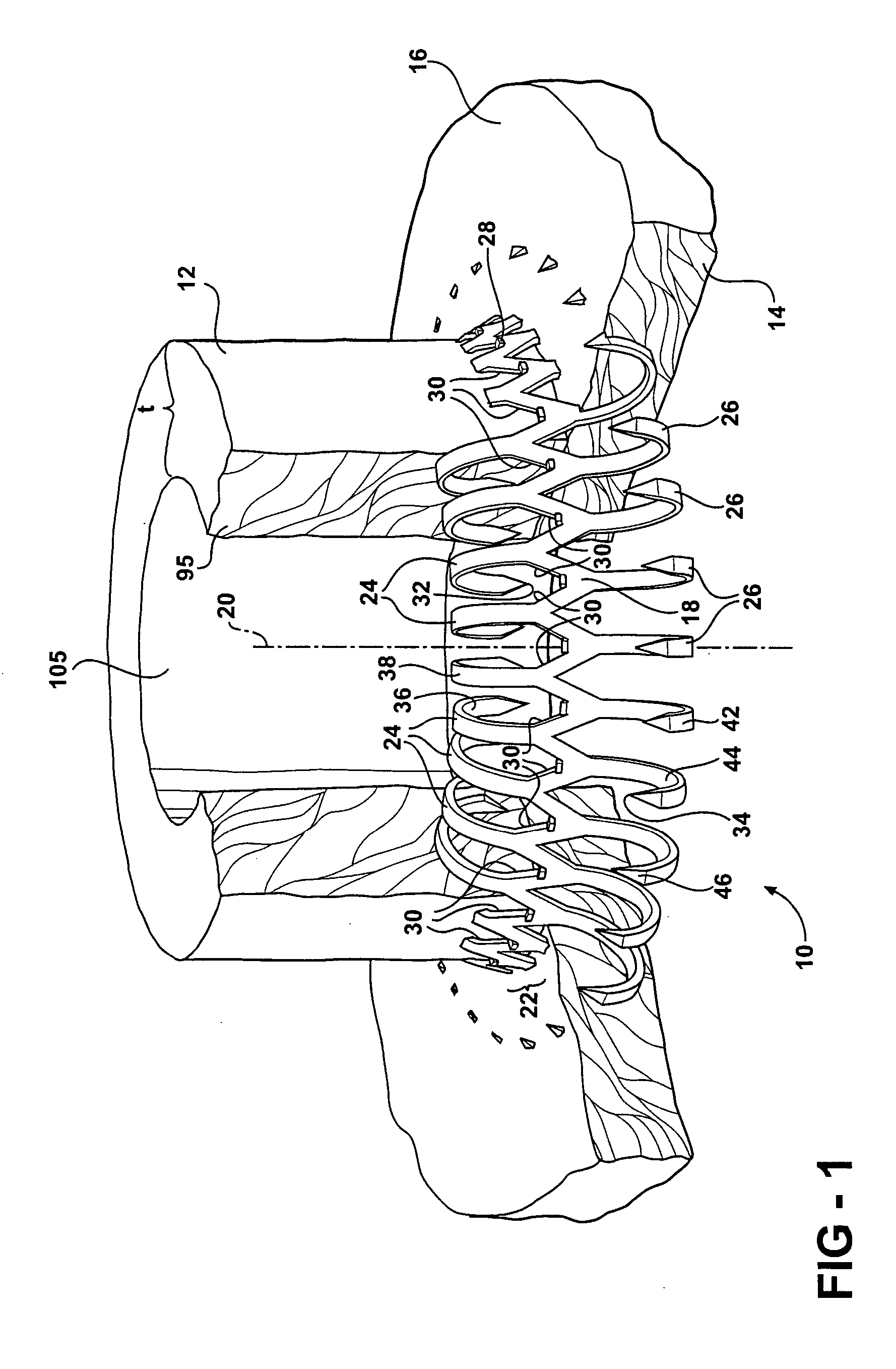
[0027] Referring to FIG. 1, an apparatus, referred to hereafter as a fastener 10, is shown making an anastomosis between two pieces of tissue, represented here as a wall 11 of a generally tubular duct 12, for example and without limitation, a graft of an artery, and a wall 14 of a vessel 16, for example and without limitation, a heart wall. The anastomosis established by the fastener 10 provides a sutureless connection between the tubular duct 12 and the vessel 16. Desirably, the fastener 10 biases the tubular duct 12 and the wall 14 of the vessel 16 toward one another, thereby establishing a leak-proof connection between the tubular duct 12 and the vessel 16. Additionally, the continual bias of the tubular duct 12 against the wall 14 of the vessel 16 facilitates the formation of a biological bond between the tubular duct 12 and the vessel 16.

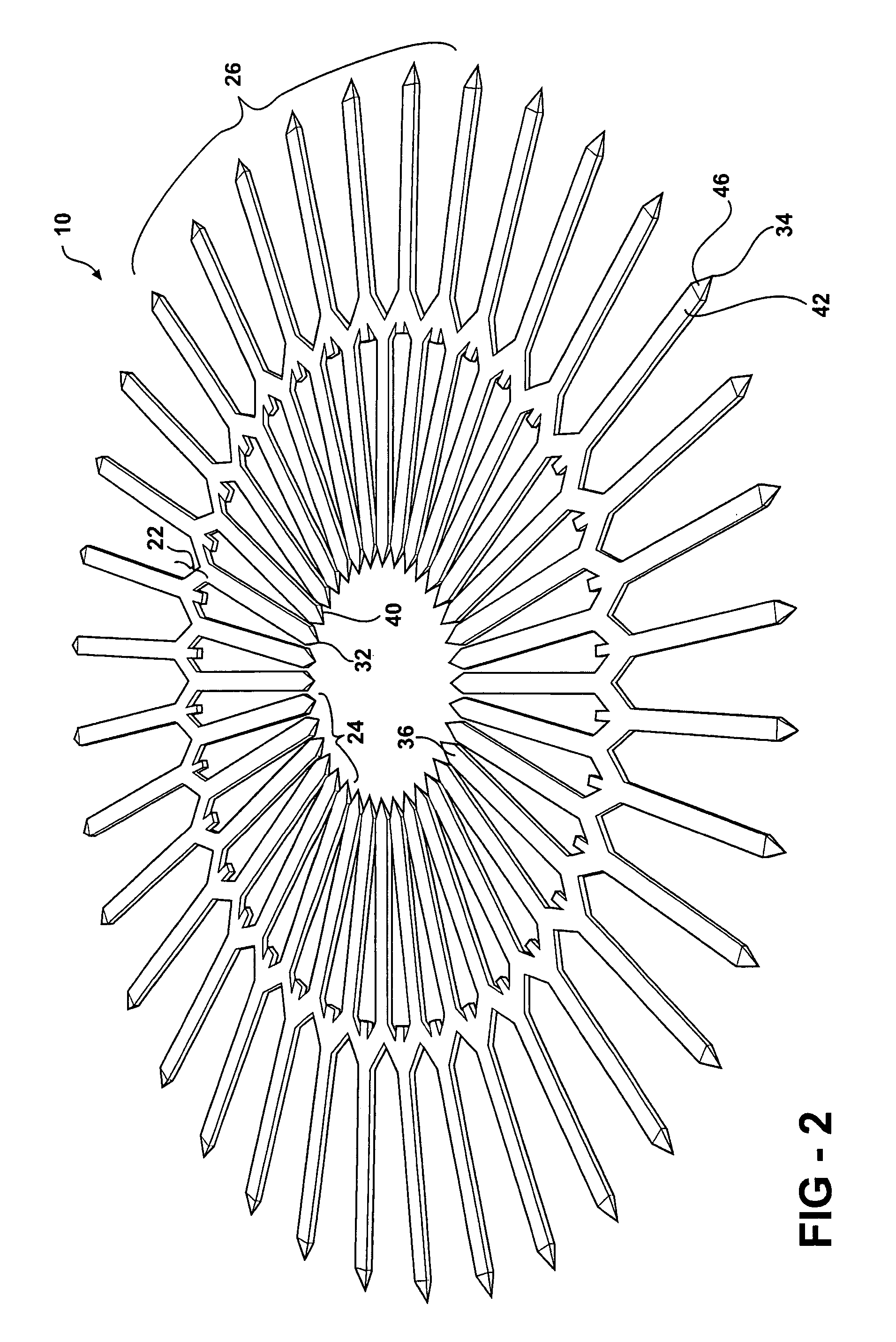
[0028] Still referring to FIG. 1, the fastener 10 has an annulus 18 with a longitudinal axis 20. The annulus 18 has a generally accordion sha...


PUM


Abstract

A method and apparatus for making an anastomosis between a tubular duct and a vessel has an annulus having a longitudinal axis, a first set of fingers and a second set of fingers. The first set of fingers extend axially from the annulus in one direction and the second set of fingers extending axially from the annulus in another direction generally opposite the direction of the first set of fingers. The first and second sets of fingers are movable to penetrate the tubular duct and the vessel, respectively, as they move from a biased configuration to an unbiased configuration.

Description

BACKGROUND OF THE INVENTION [0001] 1. Field of the Invention [0002] This invention relates generally to methods and devices for surgically joining separate pieces of tissue to one another, and more particularly to surgically joining a tubular graft of tissue to a separate piece of tissue. [0003] 2. Related Art [0004] In performing bypass surgery, it is a known practice to repair clogged or an otherwise damaged segment of tubular tissue, for example an artery, by cultivating a healthy section of artery from a remote location of the body, for example, a thigh, and replacing the damaged section with the cultivated section of artery. In addition, it is also known to bypass a clogged or damaged section of artery by rerouting a healthy section of the artery with the cultivated segment of artery attached thereto, and then attaching an end of the cultivated section of artery to another piece of tissue, for example, a wall of a heart. [0005] While performing the procedures mentioned above, a...

Claims


Application Information

Patent Timeline
Patent Type & Authority Applications(United States)
IPC IPC(8): A61B17/064A61B17/08A61B17/11A61B17/115
CPCA61B17/0644A61B17/11A61B2017/1135A61B2017/0641A61B17/115
Inventor WRIGHT, DAVID WALTER
Owner WRIGHT DAVID WALTER
Why Eureka
Try Eureka