Method and apparatus for measuring exhaust gas flow rate and it's application system for analyzing the exhaust gases from an engine

a technology of exhaust gas flow rate and measurement apparatus, which is applied in the direction of liquid/fluent solid measurement, volume/mass flow by differential pressure, instruments, etc., can solve the problems of reducing pulsation frequency, increasing error, and increasing measurement error, so as to reduce the size of the apparatus and eliminate the effect of error

Active Publication Date: 2005-04-14
HORIBA LTD
View PDF5 Cites 11 Cited by
  • Summary
  • Abstract
  • Description
  • Claims
  • Application Information

AI Technical Summary

Benefits of technology

In the emission flow rate measuring method as comprehended by the invention, it is not intended to eliminate or decrease the pulsation included in the detected differential pressure signal, but by resolving pulsation by frequency and correcting according to the frequency of pulsation, the error caused by pulsation can be corrected.
In another aspect, when the communicating part is made of a piping of 20 m or less in length and 1.0 to 50 mm in inside diameter, buffering of differential pressure by pulsation can be securely prevented by the communicating part.

Problems solved by technology

When measuring continuously the flow rate of engine emission by using the Pitot tube flowmeter, since the emission pressure (differential pressure) is measured directly, if pulsation occurs, its effect is directly applied, and the measuring error may be increased.
Although pulsation at high frequency are removed by catalyst tube or muffler, when pulsation at low frequency are caused during idling of the engine or the like, pulsation frequency is lowered, and the Pitot tube flowmeter is strongly influenced by pulsation, and the error is increased.
H10-318810, when the buffer tank is installed at the upstream side of the exhaust tube, it is not only difficult to remove pulsation completely, but also the apparatus is complicated and increased in size because it is required to form a buffer tank of variable capacity and install a mechanism for varying the capacity of the buffer tank depending on the engine rotating speed.
However, the Pitot tube flowmeter is known to have effects of pulsation of emission, and it is warned that the measuring error of emission flow rate increases due to so-called square root error occurring when calculating the emission flow rate from the differential pressure.
Such technique is not suited to the present situation and future demand because elucidation of pulsation itself and transient measurement are demanded.
It is also impossible to eliminate pulsation of emission completely by the buffer tank, and it further requires to form a buffer tank of variable capacity and mechanism for varying the capacity of buffer tank depending on the engine rotating speed, and the apparatus itself becomes complicated and larger in size.
In the gas flow measuring apparatus disclosed in Japanese Laid-open Patent No. 2000-46612, or in the flow rate measuring apparatus disclosed in Japanese Laid-open Patent No. 2001-208584, the apparatus itself is large and complicated.

Method used


Image

  • Method and apparatus for measuring exhaust gas flow rate and it's application system for analyzing the exhaust gases from an engine
  • Method and apparatus for measuring exhaust gas flow rate and it's application system for analyzing the exhaust gases from an engine
  • Method and apparatus for measuring exhaust gas flow rate and it's application system for analyzing the exhaust gases from an engine

Examples


Embodiment Construction

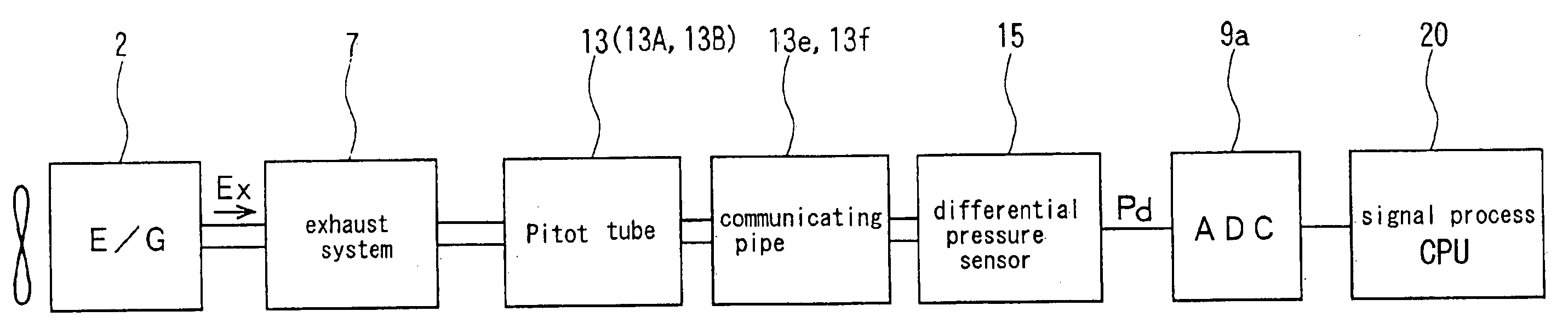
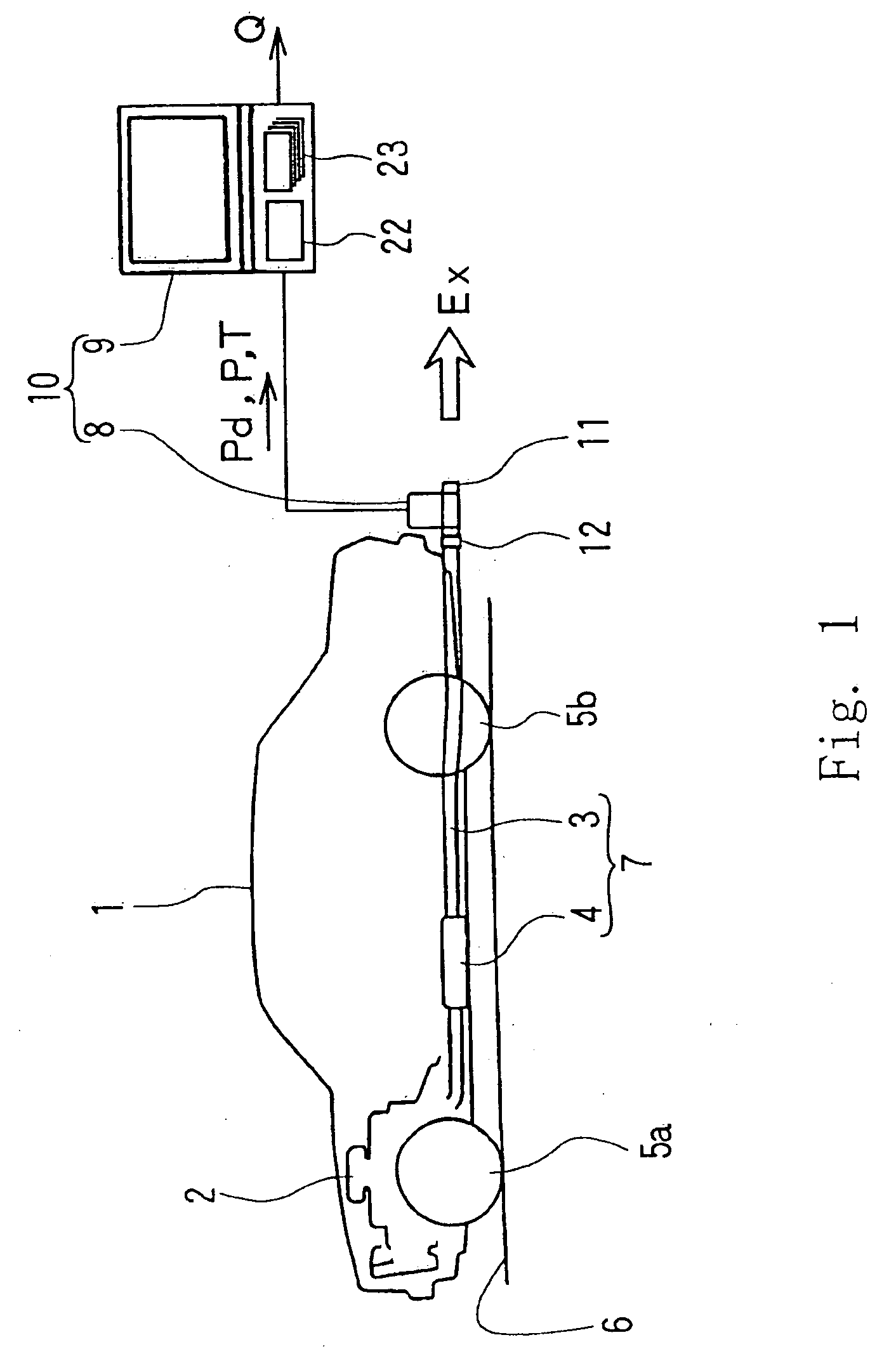
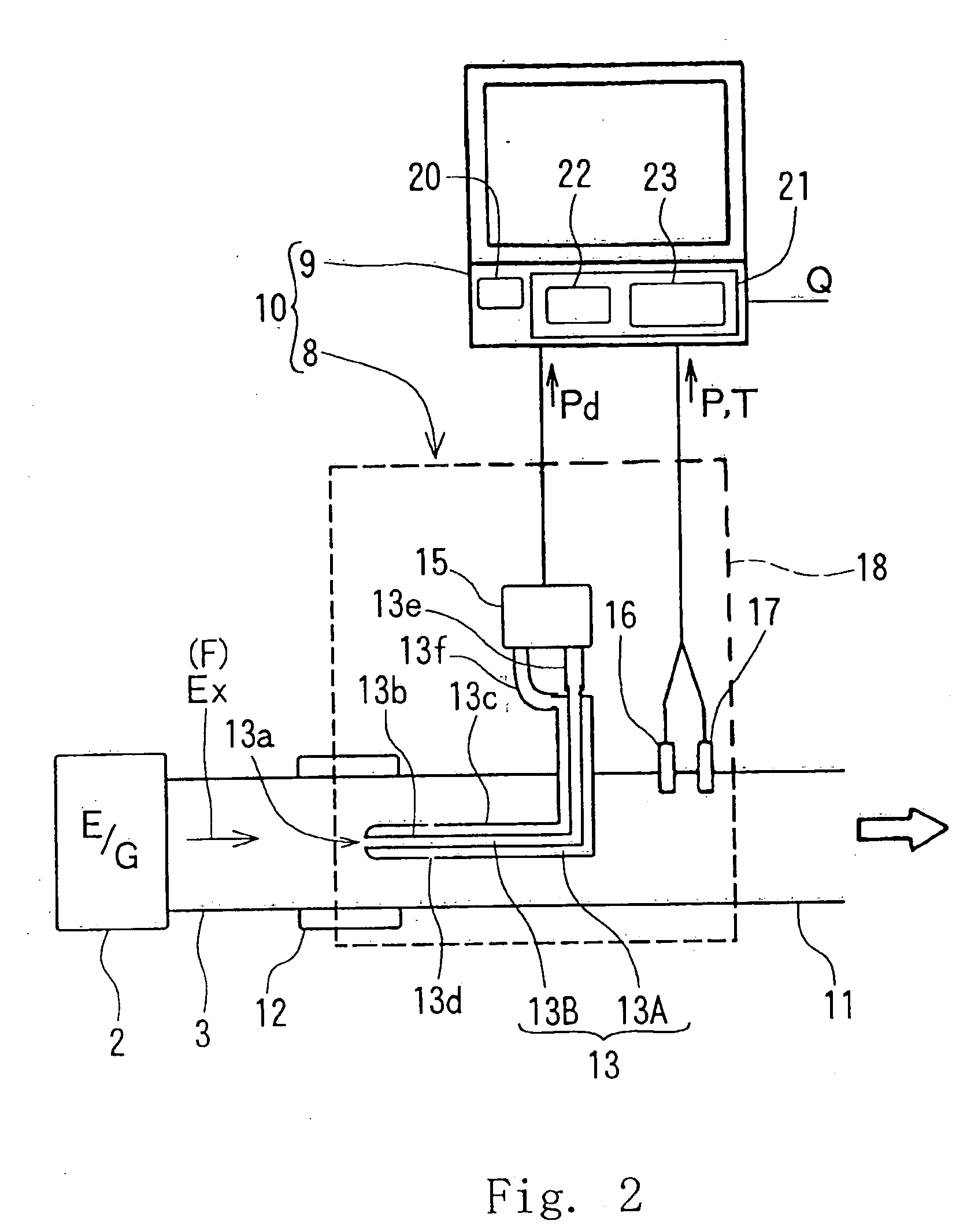
A preferred embodiment of the invention is described below while referring to the accompanying drawings. FIG. 1 is a diagram showing an example of measurement of flow rate of emission of an automobile by using a differential pressure type flow rate detecting apparatus of the invention, and FIG. 2 is an essential magnified view of the differential pressure type flow rate detecting apparatus.

In FIG. 1, reference numeral 1 is an automobile to be measured (including various types of vehicles, and called a vehicle hereinafter), 2 is an engine of the vehicle 1, 3 is an exhaust pipe as an example of flowing passage of emission Ex linked to the engine 2, and 4 is a catalyst device provided in the exhaust pipe 3. Further, reference numerals 5a, 5b are front and rear wheels, and 6 is a road surface. The exhaust pipe 3 and catalyst device 4 are parts for composing the exhaust system 7 of the vehicle 1, and the exhaust system 7 is determined according to the type of the vehicle 1.

Reference n...


PUM


Abstract

The invention presents a differential pressure type emission flow rate measuring method and apparatus and an emission measuring system using the same apparatus, capable of correcting measuring error occurring due to pulsation appropriately and enhancing the measuring precision of flow rate when measuring the flow rate of emission having pulsation. The invention, in measuring the flow rate of an emission exhausted from an engine, determines an accurate flow rate in spite of pulsation by using a differential pressure type flowmeter as the flowmeter, resolving the detected differential pressure signal by frequency, and correcting by using a correction coefficient predetermined depending on each frequency obtained by frequency resolution.

Description

BACKGROUND OF THE INVENTION 1. Field of the Invention The present invention relates to a method and apparatus for measuring exhaust gas flow rate and it's application system for analyzing the exhaust gases from automotive engine or the like. Particularly, the invention relates to a method and apparatus being capable of correcting an error caused by pulsation of flow rate by using differential pressure type flow meter, for example, the Pitot tube flow meter or the like. Moreover, backward flow rate of the above mentioned gases also distinctly can be measured by the invention. 2. Background Art A Pitot tube flowmeter is one of differential pressure type flowmeters for measuring flow rate of emission flowing in an exhaust pipe. In this Pitot tube flowmeter, gas flow rate converted to standard state Qpit (t) [m3 / min] is given in the following formula (1). In the description of the invention below, (t) is added to the sign showing a time series value by time t, and, for example, gas ...

Claims


Application Information

Patent Timeline
Patent Type & Authority Applications(United States)
IPC IPC(8): G01F1/34G01F1/46G01F1/50
CPCG01F1/34G01F1/50G01F1/46G01F1/72
Inventor NAKAMURA, HIROSHIADACHI, MASAYUKIASANO, ICHIROSENDA, JIROAOKI, SHINTARO
Owner HORIBA LTD
Why Eureka
Try Eureka